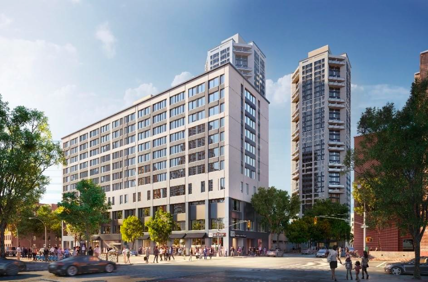
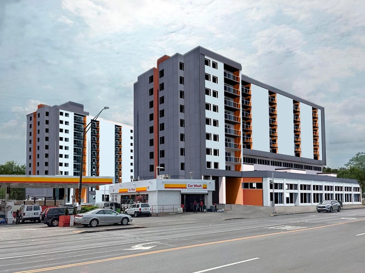
The Heritage, preserved by L+M, showcases a multifamily retrofit project that eliminates fossil fuel usage, improves resident comfort, and minimizes occupant disruption through the use of innovative retrofit methods, materials, and technology. The 34-story, three-building complex , which was built in 1974 next to Central Park in New York City, contains 600 housing units, of which 402 are affordable, with 134 set aside for the formerly unhoused.
The Heritage is an affordable housing development with poor insulation and high utility costs due to outdated heating and water heating systems. This project dramatically cuts heating and cooling needs thanks to major building envelope improvements. Packaged terminal heat pumps for heating and cooling will reduce energy use and costs from the current electric resistance heating system. The retrofit project also pilot-tests state of the art heat pump water heaters and electric laundry dryers.
L+M is a pioneer in mixed-income, market-rate, and mixed-use developments that revive and transform neighborhoods. The company has acquired, built, or preserved nearly 46,000 residential units and more than 1.2 million square feet of retail and community facility space, representing approximately $16.5 billion in development and investment.
Project Highlights
Investment
19 million
to accomplish Strategic Decarbonization retrofits.
Testimonial
“The funding from NYSERDA’s Empire Building Challenge program will help L+M pilot and scale new retrofit technologies that will drastically reduce or eliminate carbon emissions in our affordable housing portfolio. Large-scale investment in such technology is crucial to addressing the challenge of climate change.”
Joseph Weishaar
Senior Vice President
L+M Fund Management
Scale
The package of measures offers a pathway to decarbonization for LMI properties across New York State.
Testimonial
“We integrated a newer prefabricated system with EIFS to significantly upgrade the performance and aesthetics of The Heritage, while minimizing project costs.”
David Ash
Director of Construction
L+M Development Partners
Step 1
Step 1: Examine Current Conditions
A baseline assessment is key to understanding current systems and performance, then identifying conditions, requirements or events that will trigger a decarbonization effort. The assessment looks across technical systems, asset strategy and sectoral factors.
Building System Conditions
Equipment nearing end-of-life
Comfort improvements
Indoor air quality improvements
Facade maintenance
Efficiency improvements
Asset Conditions
Repositioning
Recapitalization
Capital event cycles
Carbon emissions limits
Owner sustainability goals
Market Conditions
Technology improves
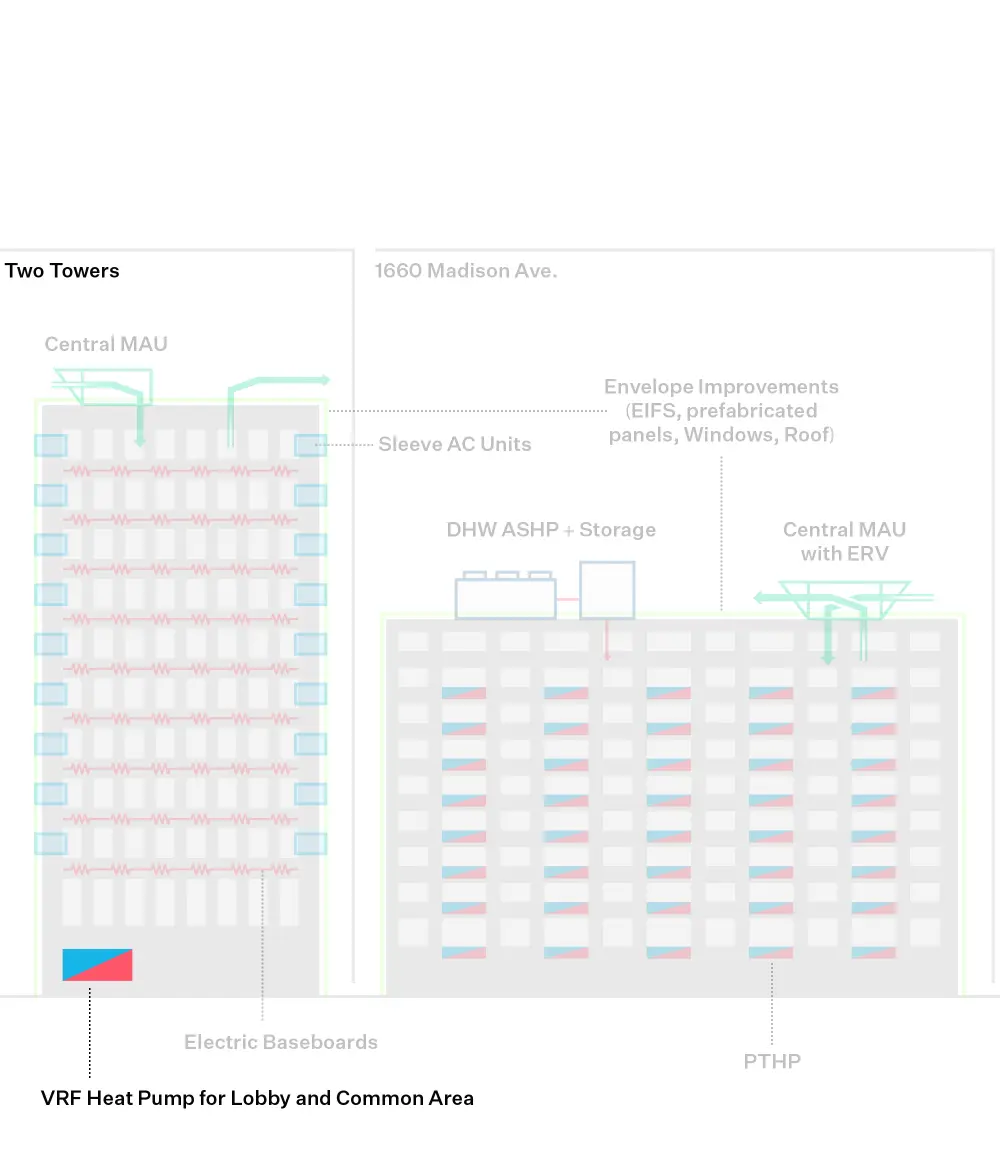
L+M takes advantage of the recapitalization cycle of The Heritage to upgrade its infrastructure and include decarbonization measures to meet its climate goals while improving tenant comfort. The property’s age and outdated design made it an ideal candidate for a deep carbon reduction project, focused on envelope improvements, high efficiency heat pumps, and an integrated design approach to minimize tenant disruption. One element of this project is improving views through larger windows.
Step 2
Step 2: Design Resource Efficient Solutions
Effective engineering integrates measures for reducing energy load, recovering wasted heat, and moving towards partial or full electrification. This increases operational efficiencies, optimizes energy peaks, and avoids oversized heating systems, thus alleviating space constraints and minimizing the cost of retrofits to decarbonize the building over time.
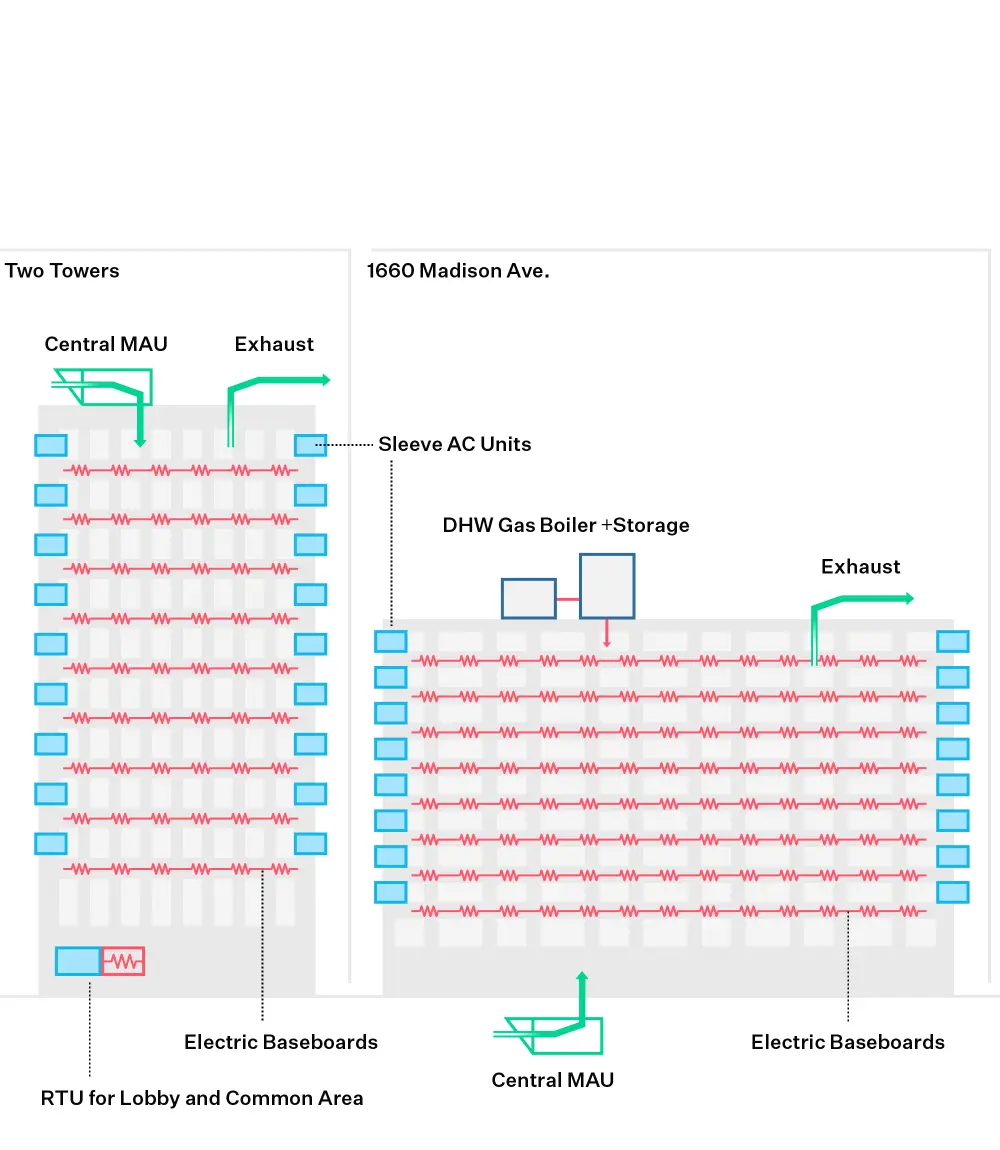
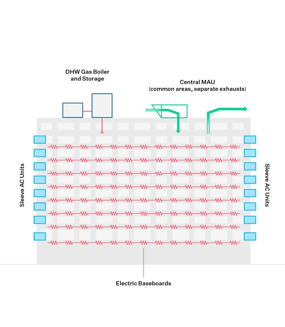
Existing Conditions
This diagram illustrates the building prior to the initiation of Strategic Decarbonization planning by the owners and their teams.
Click through the measures under “Building After” to understand the components of the building’s energy transition.
Sequence of Measures
2022
2023
2024
Building System Affected
heating
cooling
ventilation
Reduce Energy Load
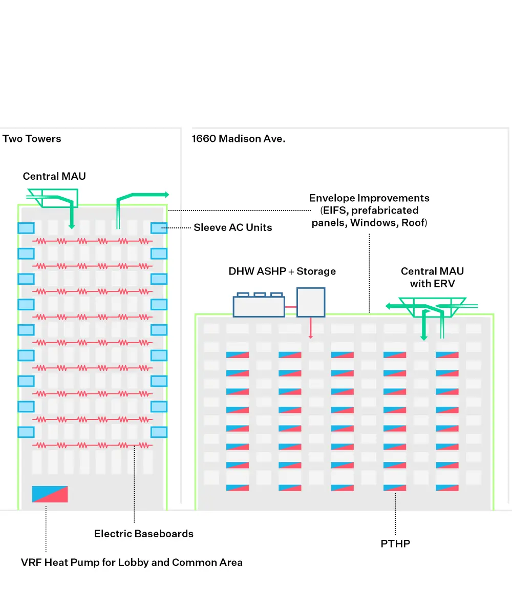
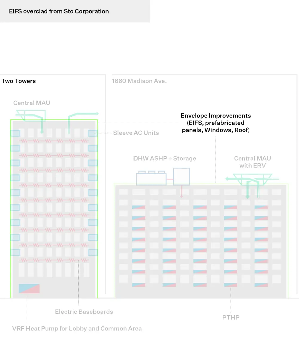
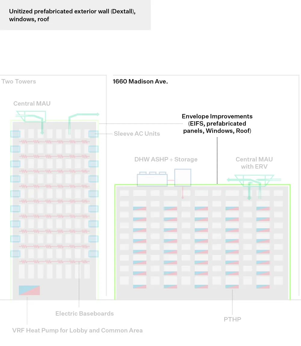
Re-cladding of the 3 buildings is estimated to avoid $10 million of LL11 compliance costs between now and 2046. One portion of the project is using prefabricated external wall panels from Dextall to minimize installation time and therefore tenant disruption.
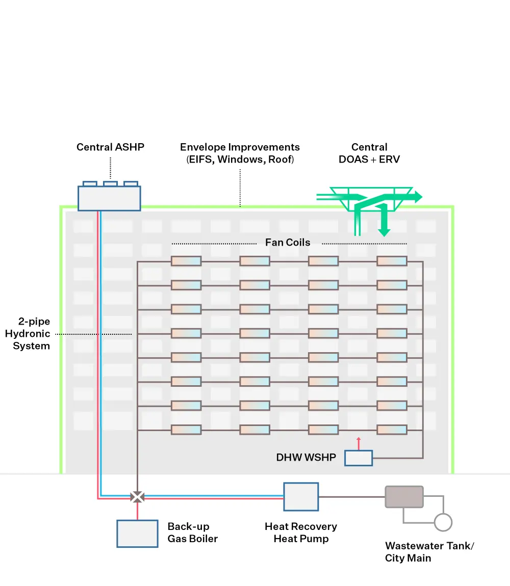
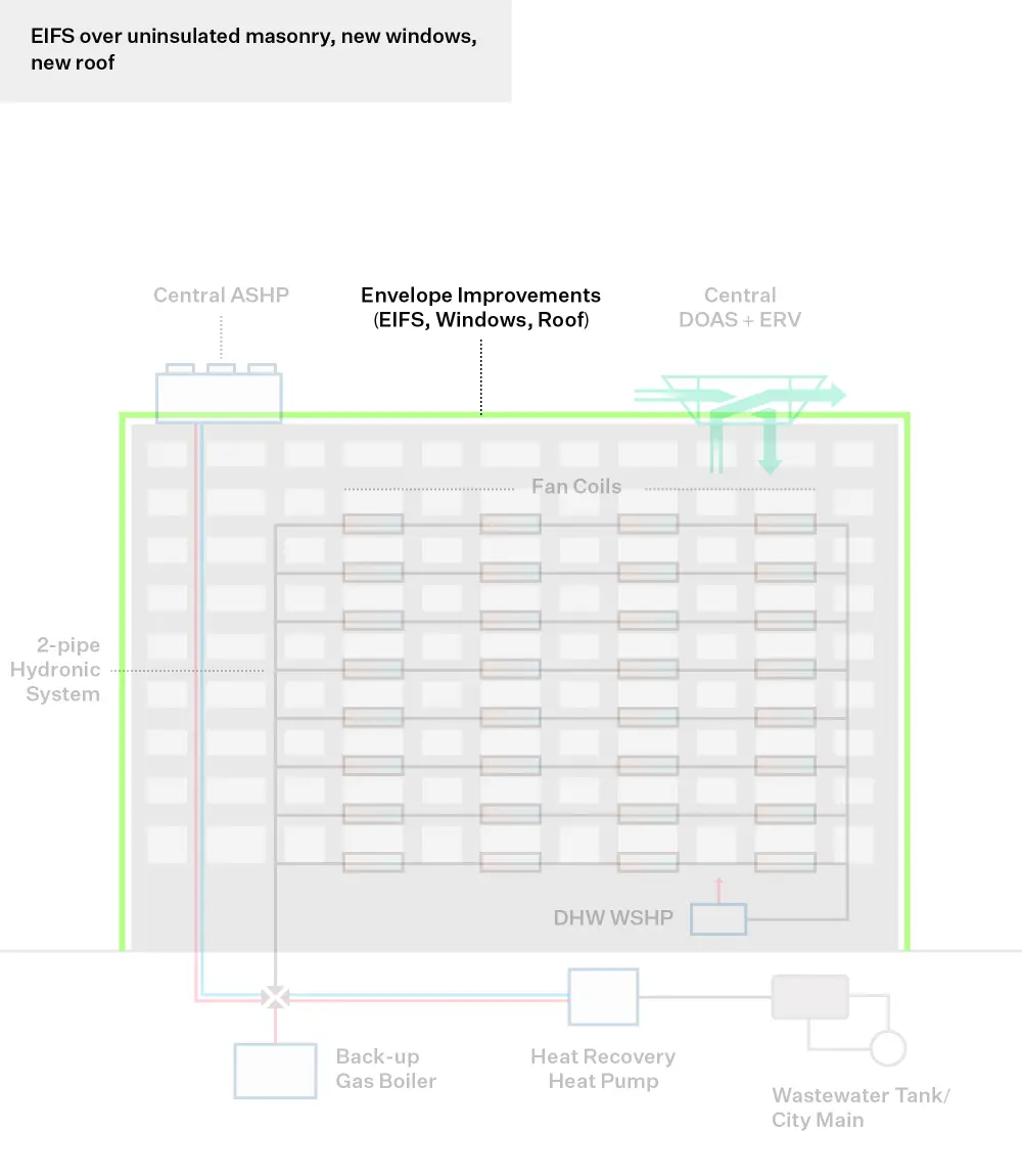
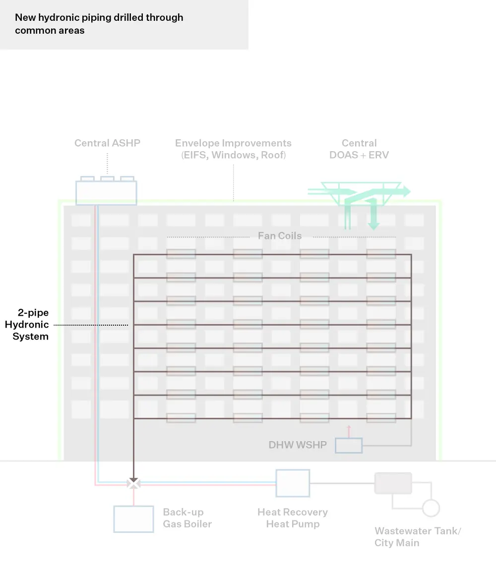
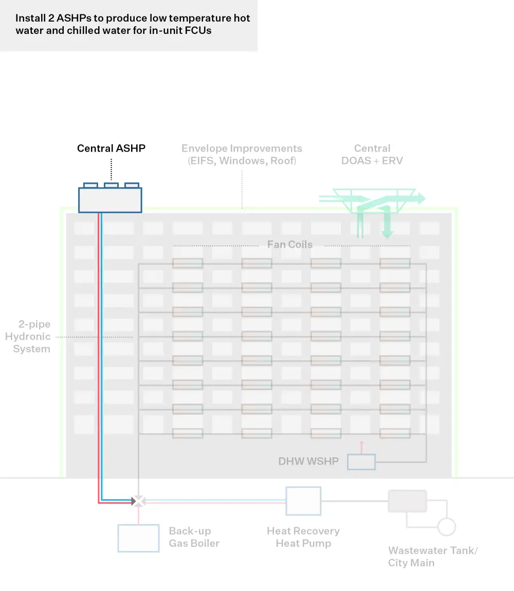
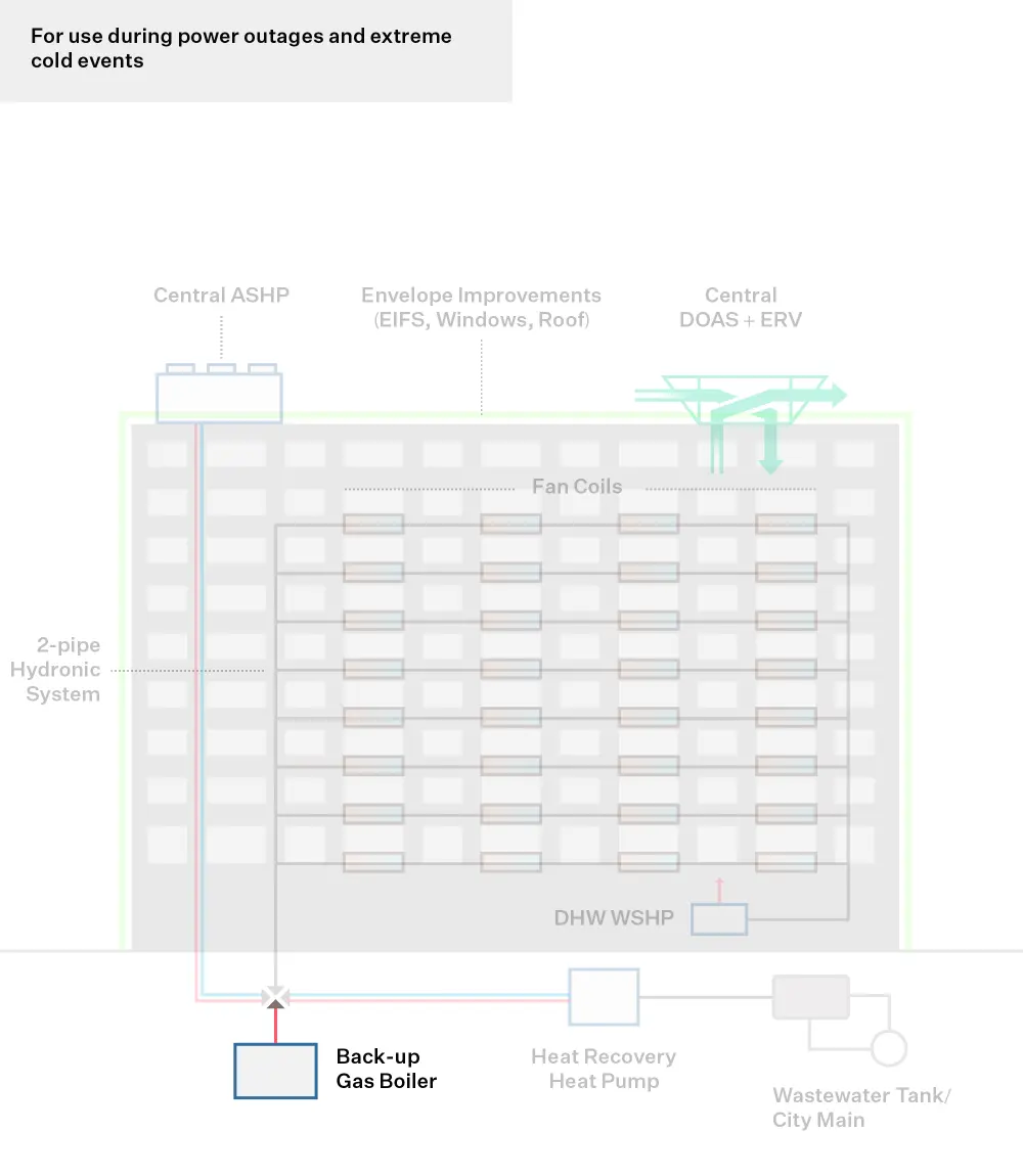
Envelope Improvement: Install exterior wall and roof insulation (EIFS overclad and panelized wall system with integrated high performance windows, dependent on location, and commercial window replacement)
Submetering
Recover Wasted Heat
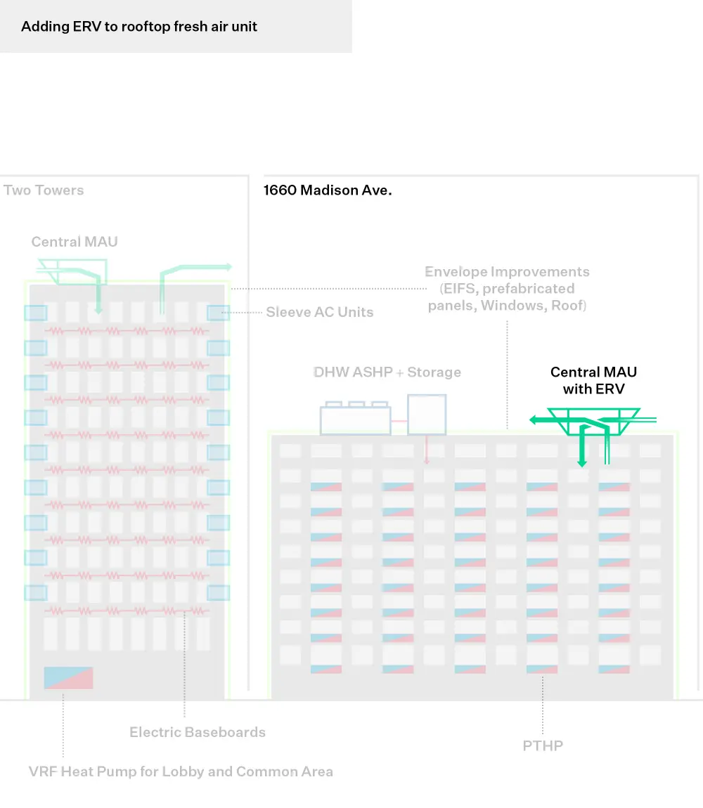
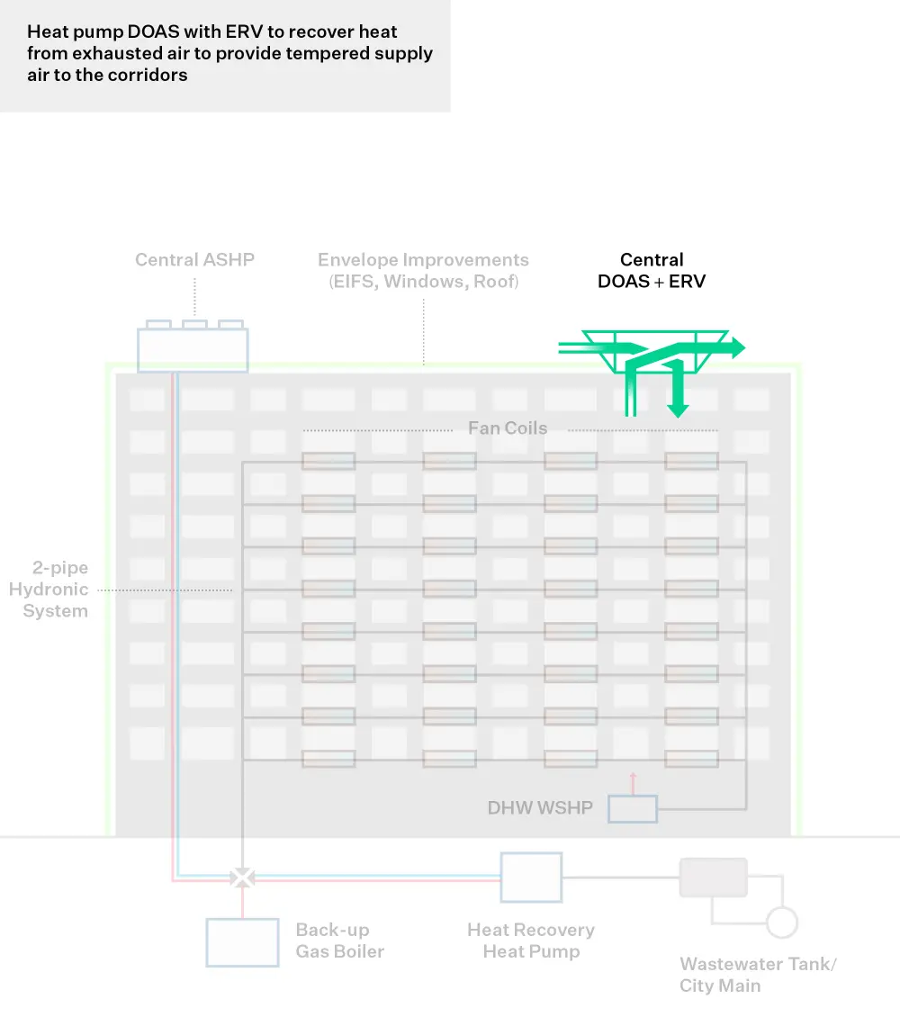
Energy Recovery Ventilator (ERV): install ERV unit into exhaust risers to recapture exhaust heat and preheat fresh air
Partial Electrification
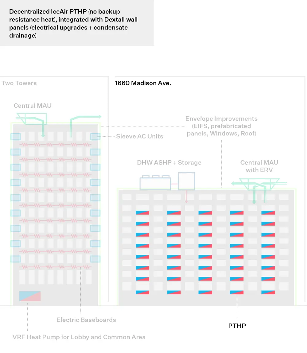
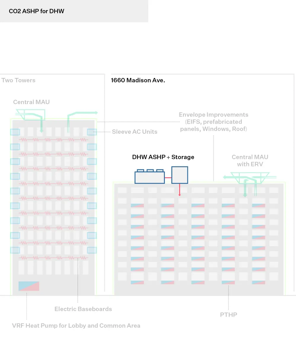
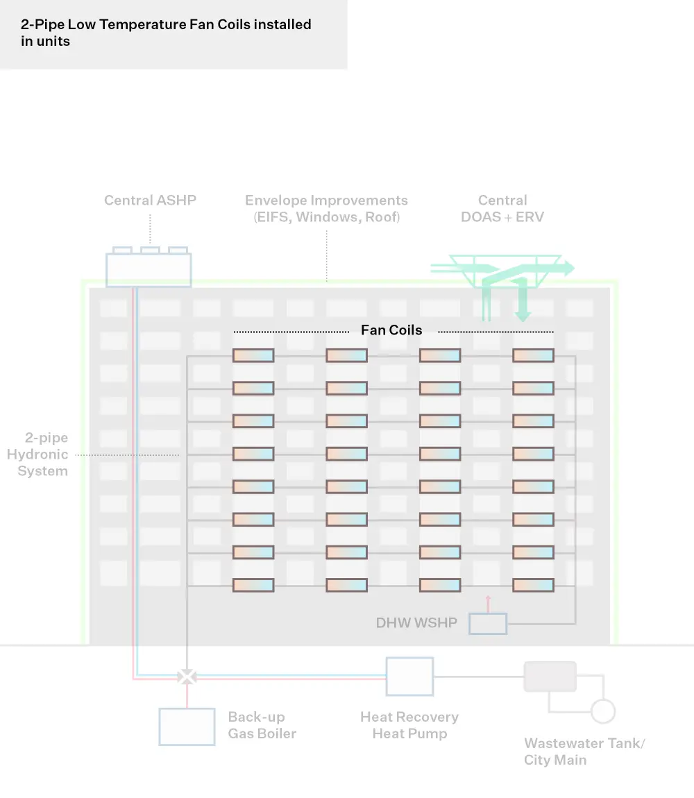
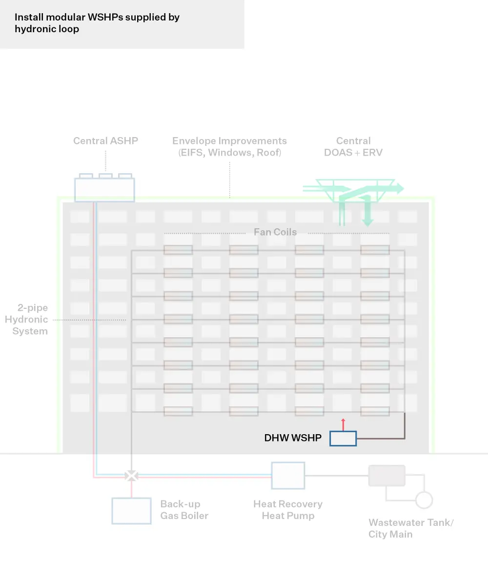
Replacing apartment electric resistance heating baseboards and sleeve air conditioning units with modular Packaged Terminal Heat Pumps (PTHP), and installing CO2-based heat pumps for Domestic Hot Water (DHW) production will significantly increase system efficiency and reduce energy use
and costs. The PTHP installation work is coordinated with the panelized exterior wall system to integrate necessary electrical upgrades and condensate lines and minimize installation time as a result.
Heat Pumps: Replace electric baseboard heating with Package Terminal Heat Pumps (PTHPs) for apartments and install VRF system for common areas
Domestic Hot Water: CO 2 Air Source Heat Pump (ASHP) for DHW production
Laundry appliance
Step 3
Step 3: Build the Business Case
Making a business case for strategic decarbonization requires thinking beyond a traditional energy audit approach or simple payback analysis. It assesses business-as-usual costs and risks against the costs and added value of phased decarbonization investments in the long-term.
Decarbonization Costs
$18M
Capital costs of decarbonization measures.
Business-as-Usual Costs
$11M + $535k / YR
BAU cost of system replacement/upgrades and LL11 compliance cost for facades + yearly energy cost, repairs, and maintenance savings.
Business-as-Usual Risks
$34k / YR
Avoided LL97 fines starting in 2030.
Decarbonization Value
$6M
Incentives from Empire Building Challenge and Clean Heat from ConEd.
Net Present Value
TBD
Net difference between the present value of cash inflows and outflows over a period of time.
Built in 1974, the buildings have little-to-no remaining insulation, costly and inefficient baseboard electric resistance heat systems, and central natural gas-fired domestic hot water (DHW) plants. The outdated design and building age make the Heritage an ideal candidate for a carbon-neutral deep retrofit.
At the time of its acquisition in late 2019, L+M planned to open up the façade at 1660 Madison to increase the size of some of the bedroom windows and replace the roof. Previous ownership had already completed this scope of work on the two high-rise towers. Since 1660 Madison was already targeted for these more intrusive upgrades, the building presented the greatest opportunity for a deep retrofit scope of work. This 11-story building’s scale and layout is representative of L+M’s portfolio and LMI (low and moderate housing) buildings in New York State.
The package cost exceeds that of standard business-as-usual practice at the property. Every element of the buildings’ envelope, HVAC systems, DHW systems, and controls are proposed for upgrades to modernize the building to meet necessary resiliency and low-carbon needs.
Standard operating practice at the building would entail maintenance and replacement of mechanical systems in-kind at end of useful life (e.g., baseboard heaters, central DHW, and exhaust equipment), and code-minimum glazing replacement at end of useful life.
The building’s heating system consists of mainly baseboard electric resistance heaters in apartments and some common areas. It is estimated that roughly 50% of the heaters date to the building’s construction and as such are past the end of useful life and in need of replacement. Cooling in apartments is provided by sleeve ACs provided by residents. PTHP installation will provide controllable, efficient heating, as well as cooling to all residents within the 1660 Madison building. The higher cost for this upgrade provides a better functioning system and benefit to residents.
The three gas-fired water heaters are near the end of their useful life, making for an ideal time to invest in a new approach to DHW. The electrification of the load at 1660 will inform the approach used at the towers later in the decarbonization period.
Facade maintenance requires continual investment. In particular, recladding of the three properties is estimated to avoid $10 million of LL11 compliance costs between now and 2046.The new façade approach will nearly eliminate these costs throughout the life of the product as it will not require the same upkeep as the existing materials.
The 1660 Madisonbuilding is an 11-story Concrete Superstructure with a masonry cavity wall façade with no insulation. The master bedrooms have one full height window and one narrow ribbon window at the top of the wall. All other bedrooms have a narrow ribbon window at the top of the wall. All the windows were replaced over 20 years ago and are in poor condition. Only the living rooms and master bedrooms are cooled, with conventional AC Units installed in through-wall sleeves.
The initial approach to updating the façade was to enlarge ribbon windows, install AC units/through-wall sleeves in all rooms without cooling, replace all residential windows, and then clad masonry with an EIFS system.
After review, it was determined that masonry columns around windows and modified openings would require a significant amount of reinforcement and likely not survive demolition and need to be removed and replaced. Construction time frames would take roughly 8 weeks per apartment with a temporary interior wall shrinking apartment spaces.
Instead L+M identified a solution that would address both the engineering and tenant challenges and found that a window-wall or panelized system would solve both. This solution eliminates the need for added masonry reinforcing and/or the rebuilding of masonry which significantly reduces installation time from (8) to (2) weeks. This allows residents to remain in their units during construction and substantially reduces the impact on their daily lives.
This approach would also give added access to upgrade the existing baseboard heating and through-wall AC cooling to combined BMS-controlled PTHPs. The façade work also permits running the necessary electrical conduit and drainage for the PTHPs. L+M identified the Dextall Dwall product which combines UPVC components resulting in superior thermal values. This prefabricated product addresses insulation and air-sealing requirements, while also including window replacements in one package. L+M verified with the manufacturer that it can be customized to include necessary sleeve penetrations for PTHPs.
Financial feasibility for decarbonization projects depends on numerous factors including the availability of project financing, incentive funding, and allocation of low-income housing tax credits (LIHTC). Exterior over-cladding projects that enhance curb appeal and improvements to resident comfort may also increase market rents and/or Section 8 rents. L+M evaluates potential reductions to long-term capital spending in addition to operating expense savings in determining which projects to pursue. In addition to financial feasibility, L+M may elect to pursue decarbonization measures in order to evaluate new materials and technologies, meet internal ESG goals, or comply with mandated or anticipated regulatory changes.
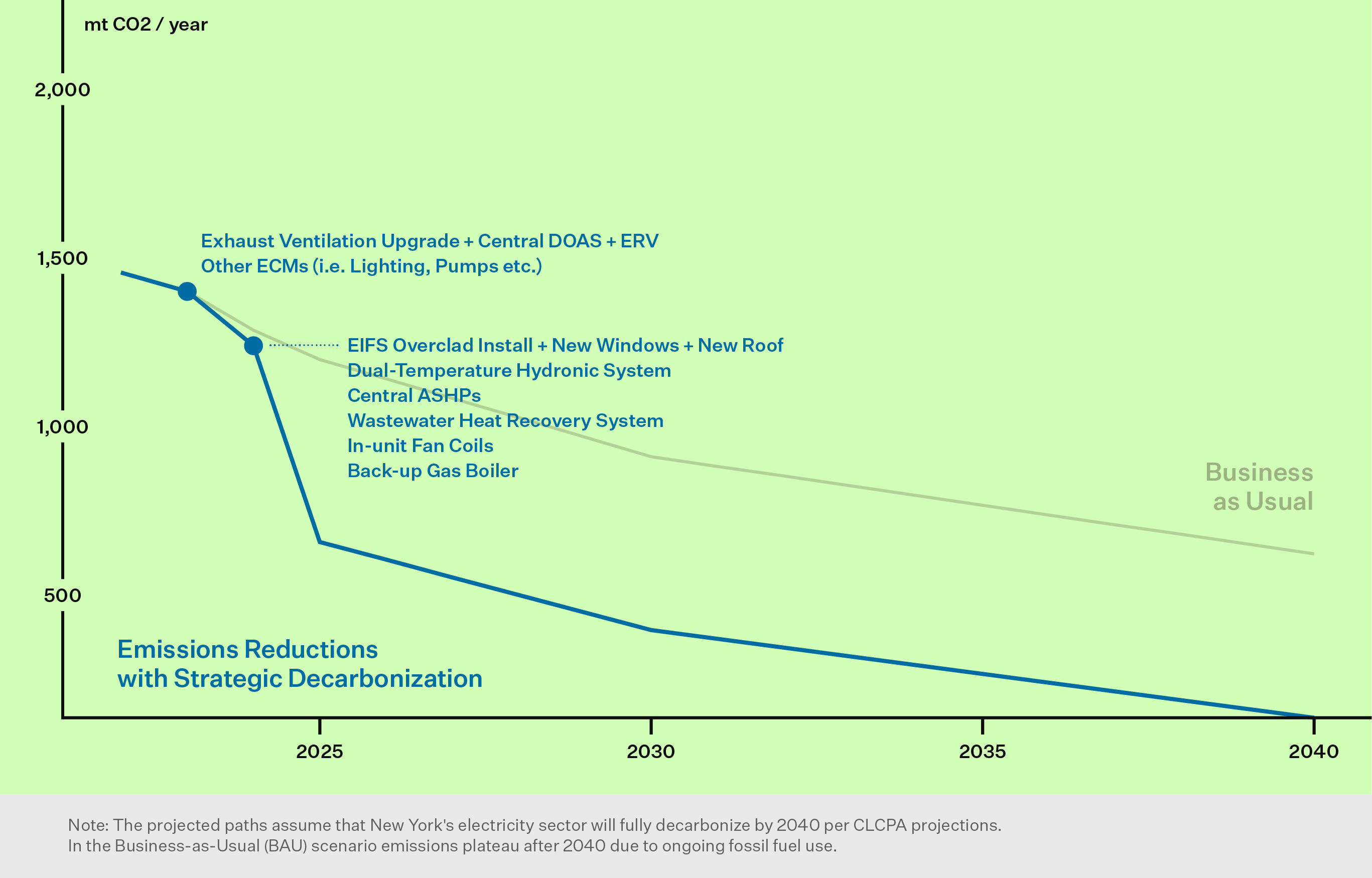
Strategic Decarbonization Action Plan
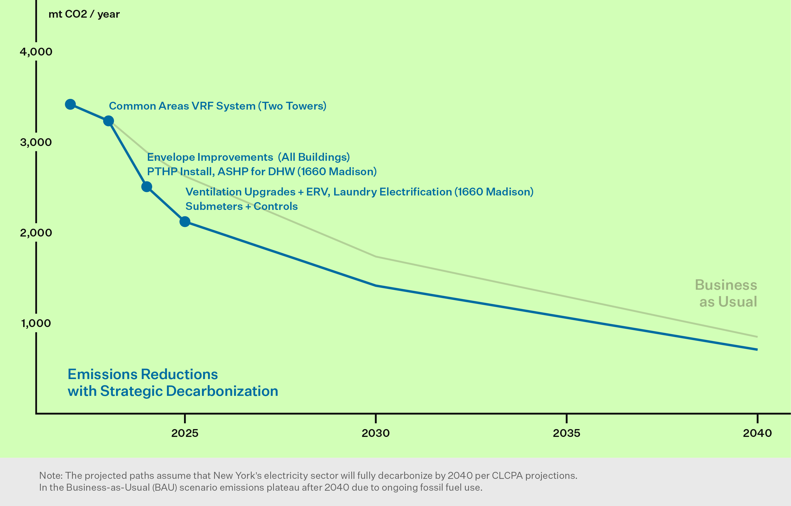
An emissions decarbonization roadmap helps building owners visualize their future emissions reductions by outlining the CO2 reductions from selected energy conservation measures. This roadmap is designed with a phased approach, considering a 20- or 30-year timeline, and incorporates the evolving benefits of grid decarbonization, ensuring a comprehensive view of long-term environmental impact.
In 2020, L+M envisioned a deep retrofit plan for the Heritage and formed its consulting team including Inglese and Cosentini. L+M and SWA discussed the possibility of applying to the Empire Building Challenge initial round to further study possibilities for the building and to support the retrofit plan. In 2021 the L+M was awarded the next round of funding to execute the vision. The process encouraged the team to think holistically about the project and identify as many opportunities as possible to eliminate fossil fuel usage, reuse waste heat, and reduce loads on the building.
Throughout 2022 to the present, the team has met regularly to review each aspect of the design, review submittals and recommend improvements, and review construction schedules and decision-making deadlines to ensure all elements of the project are completed as needed.
As a socially responsible developer, sustainability is central to L+M’s mission to create green, high-quality affordable housing. Since many of our projects are income-restricted, L+M is focused on reducing operating costs to allow for greater affordability.
Partnering with NYSERDA on developing a roadmap to carbon neutrality will benefit our investors, residents, our communities, and our environment, both now and in the future
L+M hopes to use the Empire Building Challenge as a chance to pilot new technologies and create a scalable approach to reducing emissions throughout its portfolio.
Furthermore, L+M is committed to transparency and sharing retrofit project economics and case studies with the broader industry. L+M’s pre-construction, engineering, and development teams actively share best practices with industry peers through the New York State Association for Affordable Housing (NYSAFAH), The Urban Land Institute (ULI) and other industry organizations.
L+M is also an active participant in conferences and stakeholder sessions with NYSERDA and is committed to working with state and local governments, equipment suppliers, contractors, and the broader real estate industry to decarbonize the built environment.
A baseline assessment is key to understanding current systems and performance, then identifying conditions, requirements or events that will trigger a decarbonization effort. The assessment looks across technical systems, asset strategy and sectoral factors.
Building System Conditions
Asset Conditions
Market Conditions
Step 2
Step 2: Design Resource Efficient Solutions
Effective engineering integrates measures for reducing energy load, recovering wasted heat, and moving towards partial or full electrification. This increases operational efficiencies, optimizes energy peaks, and avoids oversized heating systems, thus alleviating space constraints and minimizing the cost of retrofits to decarbonize the building over time.
Step 3
Step 3: Build the Business Case
Making a business case for strategic decarbonization requires thinking beyond a traditional energy audit approach or simple payback analysis. It assesses business-as-usual costs and risks against the costs and added value of phased decarbonization investments in the long-term.
Decarbonization Costs
Business-as-Usual Costs
Business-as-Usual Risks
Decarbonization Value
Net Present Value
Strategic Decarbonization Action Plan
An emissions decarbonization roadmap helps building owners visualize their future emissions reductions by outlining the CO2 reductions from selected energy conservation measures. This roadmap is designed with a phased approach, considering a 20- or 30-year timeline, and incorporates the evolving benefits of grid decarbonization, ensuring a comprehensive view of long-term environmental impact.
Project Team
Additional Resources
Tags
Insights from Empire Building Challenge
Improved engineering design means and methods are needed to enable and speed adoption of low-carbon retrofit technologies. High performance, low-carbon heating and cooling systems are widely available but are underutilized in the United States due to a variety of misconceptions and a lack of knowledge around thermal system interactions. Few practicing engineers prioritize recycling heat and limiting heat loss. Decarbonization requires upgrading and adapting energy distribution systems originally designed to operate with high temperature combustion to integrate with electric and renewable thermal energy systems. The engineering design industry can use a thinking framework like Resource Efficient Decarbonization (RED) to deliver projects that achieve more effective decarbonization.
This framework emerges from the Empire Building Challenge through continued collaboration among real estate partners, industry-leading engineering consultants, and NYSERDA. RED is a strategy that can help alleviate space constraints, optimize peak thermal capacity, increase operational efficiencies, utilize waste heat, and reduce the need for oversized electric thermal energy systems, creating retrofit cost compression. While RED is tailored to tall buildings in cold-climate regions, the framework can be applied across a wide array of building types, vintages, and systems. The approach incorporates strategic capital planning, an integrated design process, and an incremental, network-oriented approach to deliver building heating, cooling, and ventilation that:
Requires limited or no combustion,
Enables carbon neutrality,
Is highly efficient at low design temperatures and during extreme weather,
Is highly resilient, demand conscious, and energy grid-interactive,
Reduces thermal waste by capturing and recycling as many on-site or nearby thermal flows as possible, and
Incorporates realistic and flexible implementation strategies by optimizing and scheduling phase-in of low-carbon retrofits competing with business-as-usual.
Decarbonization Framework
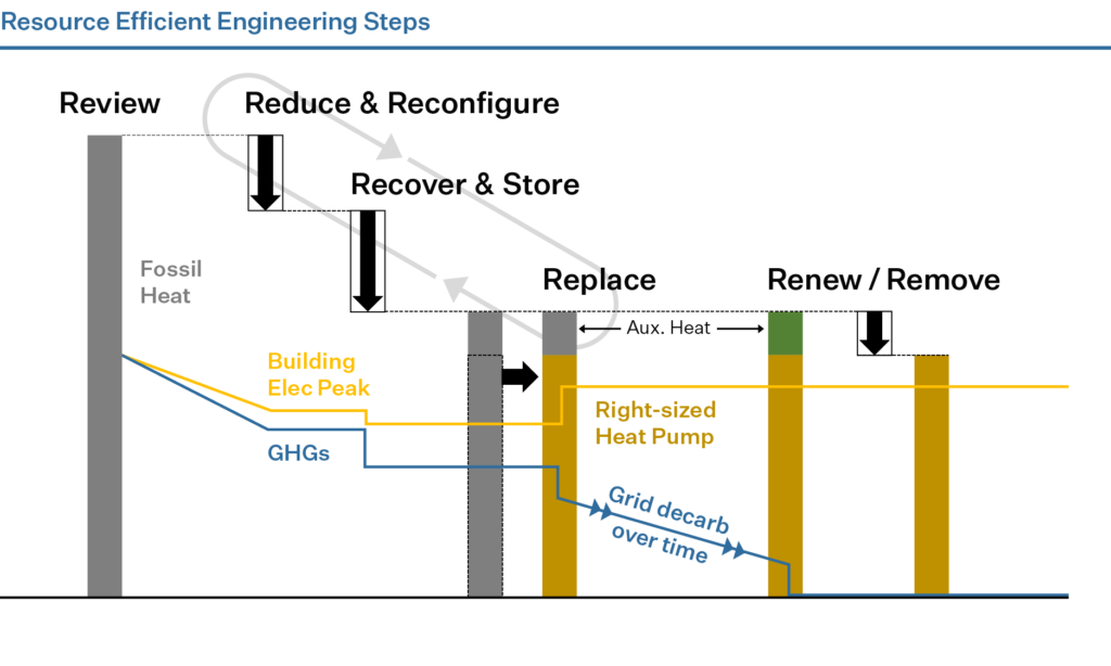
Resource Efficient Decarbonization focuses on implementing enabling steps that retain a future optionality as technology and policy evolves. This framework allows a building owner or manager to take action now, instead of waiting for better technology and potentially renewing a fossil-fueled powered energy system for another life cycle.
The figure below illustrates a conceptual framework for accomplishing these objectives and overcoming the barriers. Specific measures and sequencing will be highly bespoke for a given building, but engineers and their owner clients can use this bucketed framework to place actionable projects in context of an overarching decarbonization roadmap.
Step-by-Step Process to Advise Decarbonization Efforts
Understanding a building’s fossil fuel use in detail is a critical first step. Make an effort to understand when, where, how, and why fossil fuels are being consumed at the building and under what outdoor temperature and weather conditions. Conduct a temperature BINS analysis to know how much fossil fuel is consumed during various temperature bands (typically in 5- or 10-degree increments) from design temperature up to the end of the heating season. Make an effort to understand cooling season usage patterns in detail. Go further and conduct an 8760 hour/year analysis or modeling effort to show building operation profiles with high granularity to advise targeted elimination of fossil fuel consumption.
While electrification is desirable to combat climate change, energy efficiency is a critical component of decarbonization. Reducing heating and cooling loads across all weather conditions is a major early step to achieve RED.
Identify the ways heat is being gained or lost. Hint: some places to look at are cooling towers, facades and windows, elevator machine rooms, through sewer connections, or at the ventilation exhaust system. Cooling towers operating in the winter are an obvious energy wasting activity. Seek solutions to reduce, recover, and recycle or reuse, and store this heat.
After, or in parallel with the previous steps, begin to electrify the building heat load, starting with marginal “shoulder season” loads (spring and fall). Don’t force electric heating technology such as air source heat pumps to operate during conditions for which they weren’t designed. Optimize heat pump implementation through a “right sizing” thermal dispatch approach to avoid poor project economics and higher operating expenses. This means continuing to retain an auxiliary heating source for more extreme weather conditions until fossil fuels are ready to be fully eliminated. This approach provides owners time to identify the right peak period heating solution while allowing them to act early in driving down emissions. Emissions reduced sooner are more valuable than emissions reduced in the future.
Remove connections to fossil fuels and meet decarbonization deadlines!
Take Actions with these Enabling Steps
Review
Disaggregate time-of-use profiles to identify heat waste and recovery opportunities and to right-size equipment.
Thermal dispatch strategy: layering heat capacity to optimize carbon reduction and project economics.
Reduce
Repair, upgrade and refresh envelopes.
Optimize controls.
Reconfigure
Eliminate or reduce inefficient steam and forced air distribution.
Create thermal networks and enable heat recovery.
Lower supply temperatures to ranges of optimal heat pump performance.
Segregate and cascade supply temperatures based on end-use.
Recover
Simultaneous heating and cooling in different zones of building.
Eliminate “free cooling” economizer modes.
Exhaust heat recovery; absorbent air cleaning.
Building wastewater heat recovery.
Municipal wastewater heat recovery.
Steam condensate.
Refrigeration heat rejection.
Other opportunistic heat recovery and heat networking.
Store
Store rejected heat from daytime cooling for overnight heating.
Store generated heat— centrally, distributed, or in the building’s thermal inertia.
Deploy advanced urban geothermal and other district thermal networking solutions.
Building Systems Topologies
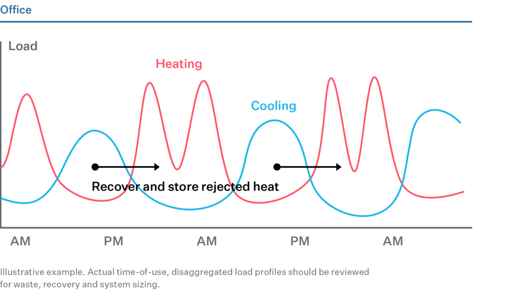
Commercial Office
Commercial office buildings offer significant heat recovery and storing opportunities due to simultaneous heating and cooling daily profiles. As a result, offices can heat themselves much of the year with heat recovery and storage. Example load profiles for typical heating and cooling days in a commercial office building are shown in the graph below.
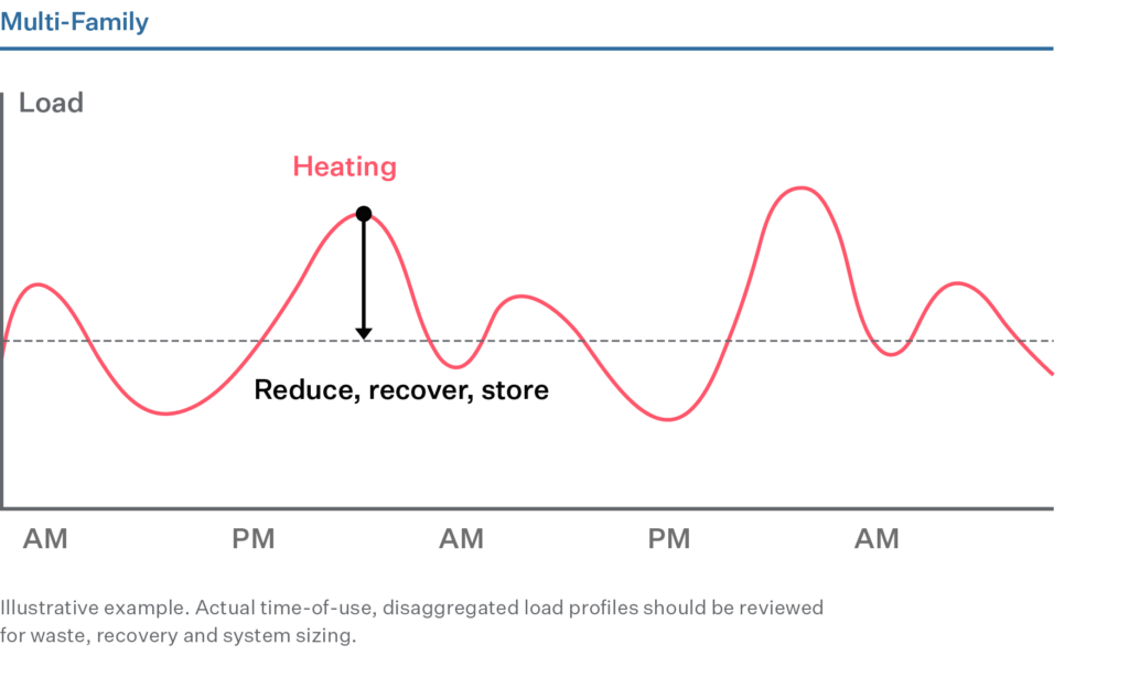
Multi-family
Multi-family buildings’ typical daily profiles show efficiency opportunities that can lower and flatten system peaks. This can be achieved by a variety of heat reduction, recovery, and storing strategies. Example load profiles for a typical heating day in a multifamily building are shown in the graph below.
Thermal Distribution Opportunities
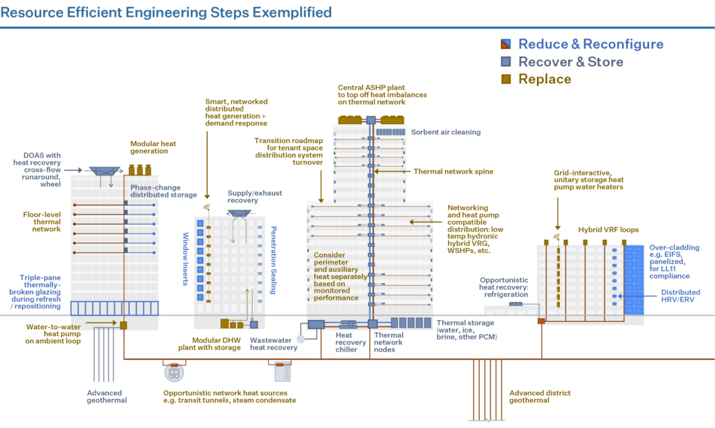
The thermal energy network approach enables transaction of thermal energy to increase overall system efficiency and reduce wasted heat. The concept can be applied at the building level (with floor-by-floor heat exchange), to groups of buildings, to whole neighborhoods, or to cities. Below is an illustration of a whole-system, thermal network approach applied in an urban environment to supply clean heat in cold-climate tall buildings:
A baseline assessment is key to understanding current systems and performance, then identifying conditions, requirements or events that will trigger a decarbonization effort. The assessment looks across technical systems, asset strategy and sectoral factors.
Building System Conditions
Asset Conditions
Market Conditions
Step 2
Step 2: Design Resource Efficient Solutions
Effective engineering integrates measures for reducing energy load, recovering wasted heat, and moving towards partial or full electrification. This increases operational efficiencies, optimizes energy peaks, and avoids oversized heating systems, thus alleviating space constraints and minimizing the cost of retrofits to decarbonize the building over time.
Step 3
Step 3: Build the Business Case
Making a business case for strategic decarbonization requires thinking beyond a traditional energy audit approach or simple payback analysis. It assesses business-as-usual costs and risks against the costs and added value of phased decarbonization investments in the long-term.
Decarbonization Costs
Business-as-Usual Costs
Business-as-Usual Risks
Decarbonization Value
Net Present Value
Strategic Decarbonization Action Plan
An emissions decarbonization roadmap helps building owners visualize their future emissions reductions by outlining the CO2 reductions from selected energy conservation measures. This roadmap is designed with a phased approach, considering a 20- or 30-year timeline, and incorporates the evolving benefits of grid decarbonization, ensuring a comprehensive view of long-term environmental impact.
Project Team
Additional Resources
Tags
Insights from the Empire Building Challenge
A calibrated energy model should play a central role in building out a decarbonization plan because it provides insights on:
Current building energy and carbon profiles, and costs.
Potential energy, carbon, and cost savings of energy conservation measures (ECMs.
The impact of groups of ECMs, and the order of implementation and timeline.
The steps to follow include:
An initial energy model is developed using commonly available building information such as architectural floorplans, MEP schedule sheets, and BMS sequences of operation.
The initial model is then refined and “calibrated” to the building’s real utility data for each utility consumed, creating a baseline condition that ECM’s will be compared against.
The baseline energy model is used as a test bed for individual ECMs to understand potential energy, carbon, and cost impacts.
Evaluate the financial performance of each ECM. These results will be used to identify strategies that are economically viable and should be considered further.
Those ECMs that are economically viable on their own may be grouped together with other ECMs to help build a holistic business case for system optimization and maximum carbon reduction.
During the evaluation process, the project team should take the evolving emission factors associated with utilities such as electricity and steam, as well as the impact of rising average and design day temperatures/humidity, into account.
Key outputs from the energy modeling workflow should include data driven charts showing energy end use breakdown and costs, carbon footprint of each utility, building carbon emissions vs. LL97 targets and fines, and who “owns” the carbon footprint (i.e. tenants, building operations). It is important to note that not all energy models are created equally. For a deep energy retrofit project, the accuracy of the energy model should align with ANSI/ASHRAE/IES Standard 90.1. Code or LEED energy models that were developed for the building in the past are not appropriate for this effort.
Below is a selection of the energy modeling software packages used to support the case study findings presented in this Playbook, and throughout the industry.
An energy model is developed in multiple phases. In the first phase, the energy modeler must build an initial model that captures the geometry, material attributes, occupancy types, MEP systems and basic information about the building’s operations. The energy modeler should also include surrounding buildings that may impact sun exposure on the different facades of the building under study. This initial model will produce a rough estimate of how the building performs every hour during the year. Then in the next phase, the energy modeler must hone the model’s accuracy by “calibrating” the initial model to utility data and detailed building operations information. Code or LEED energy models that may have been created for the building during its initial design and construction should not be used in deep energy retrofit study efforts because they do not reflect the actual performance of the building under study.
Lessons Learned and Key Considerations
Determine energy model accuracy expectations early: Energy model accuracy can vary widely. For a deep energy retrofit study, the energy model should be highly accurate and align with ANSI/ASHRAE/IES Standard 90.1. Building management teams should set model accuracy expectations with the energy modeler at the onset of the project. This will help inform how assumptions are made and where the modeler should or should not simplify certain aspects of the model.
Energy model calibration takes time but is worth the investment: Calibrating the initial energy model is a continuous and iterative process that can span multiple days or weeks depending on the complexity of the building. This time investment is well worth it because the quality of the energy modeling results is directly dependent on the quality of the calibration effort.
Sync energy modeling assumptions with site observations: Even well-maintained buildings with stringent base-building and tenant standards have operational nuances and anomalies. Equipment may be shut off or sequences may be manually overwritten because the system wasn’t commissioned, wasn’t correctly integrated with the BMS, or was causing a localized issue that required a quick fix. This is especially true for older existing buildings that have had operations team turnover resulting in a loss of institutional knowledge over the years. For the energy model to accurately capture savings for ECMs, the calibrated model must reflect real-life operation. The project’s energy modeler should capture these nuances in the calibrated model whenever possible.
Perfection is the enemy of “good enough”: The energy model will never perfectly simulate the performance of the building. There will also be a margin of error that comes from very specific nuances in building construction or operation that can’t be captured by simulation-based software. The project team should set reasonable expectations for the level of modeling and calibration effort that aligns with AANSI/ASHRAE/IES Standard 90.1 but also conforms to the project schedule and status.
Share model visualization with the project team: Energy modeling can be a complex topic that may seem inaccessible to non-technical audiences. To maintain good project team engagement during the energy modeling phase, the energy modeler should prepare and share data visualizations that can help tell the story of how the building uses energy. Graphs, rendering, and infographics are great examples of visual assets that can demystify the energy modeling process.
2. Create the Baseline Energy Model
The baseline model represents the current systems and operations of the building, adjusted for “typical” weather conditions and other criteria. Energy savings for all proposed ECMs will be calculated relative to the baseline model performance.
Inputs
The calibrated energy model
TMY weather data
List of planned upgrades, tenant lease turnover schedules
Activities
Make Necessary Adjustments to the Baseline Model: To create a baseline energy model, the calibrated energy model consumption should be adjusted to account for the following:
Weather: Typical weather data for the site can be modeled using TMY3 data files, which capture and compare typical performance and eliminate any extreme weather event effects that may have occurred in the baseline year. TMY3 files are produced by the National Renewable Energy Laboratory and can be freely accessed and downloaded from the EnergyPlus website.
Occupancy (Lease Turnover or COVID): The baseline energy model should be adjusted to account for any fluctuations in building occupancy that are expected to occur over the study period. For example, tenant lease turnover schedules should be collected during the Discovery Phase and accounted for in the baseline model. Similarly, any disruptions to building occupancy, such as those experienced during the COVID 19 global pandemic, should be captured in the baseline model. To understand the full magnitude of ECM impacts, it is important to separate energy reductions resulting from ECMs versus those resulting from lower occupancy levels.
Planned Upgrades: The baseline model should be adjusted to account for any planned projects that will impact the building’s energy consumption. By capturing these savings in the baseline model, the project team will avoid projecting ECM savings that are no longer available because they have already been captured by planned projects.
The baseline model represents “business as usual” building energy consumption and associated energy cost. It is the reference point used to determine the energy savings of potential ECMs and track progress towards reaching project objectives.
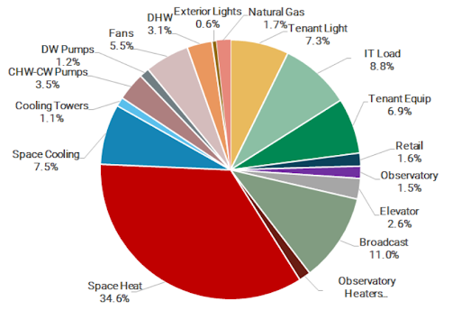
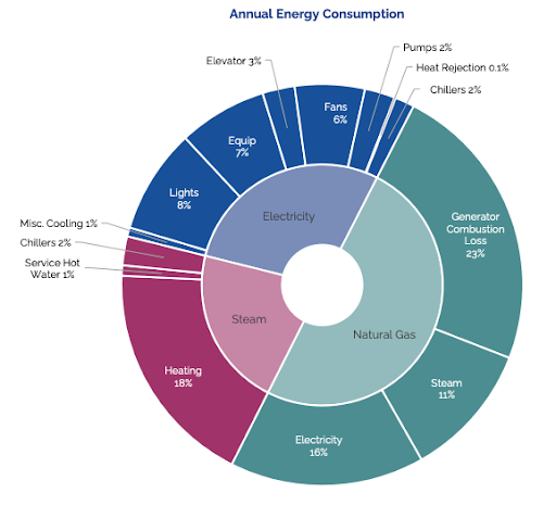
Generate Detailed End-Use Breakdowns: Once the baseline energy model is complete, the project team can begin to gain additional insight into how the building uses energy. A particularly useful output of the model is a detailed end-use breakdown like the one shown below:
The energy modeler will be able to analyze this end use breakdown and identify systems that appear to be high energy consumers. Hypotheses should be vetted by the engineer and facilities team based on their understanding of the building.
Document Assumptions and Review Initial Results with the Team: After the initial baseline model has been built, the energy modeler should review his/her/their assumptions and the resulting load breakdowns with the project team. The modeler should then solicit feedback from the engineers and building operators who have greater insight into the current building operation and systems design. Feedback should be incorporated into the next iteration of the baseline model. The feedback loop between the energy modeler and the building team will be an iterative process that will continue throughout the duration of the project as more information is collected from the building.
Overlay Carbon Emissions: Once the baseline energy consumption results are refined, the associated operational carbon emissions can be calculated by multiplying the annual energy consumption by a fuel-specific carbon coefficient. Carbon coefficients represent the greenhouse gas emissions intensity of different energy sources and are used to determine a building’s total greenhouse gas emissions in tons of CO2 equivalent. This analysis will identify the primary contributors to greenhouse gas emissions in terms of fuel type, system, and ownership (end-user that is driving the demand).
Refine the Preliminary List of ECMs: At this point, the energy modeler and engineer should work together to refine the preliminary list ECMs that was developed in the “Build the BAU Base Case” task. The additional information gleaned from the detailed end use breakdown should be used to validate the initial list of measures and to identify new areas of focus that were not identified in early phases of the project.
Outputs
Deliverables from the baseline energy model work include the following:
Baseline energy model is a reference for potential energy, carbon and cost savings
Building energy consumption and detailed end use breakdowns
Documented baseline system assumptions
Finalized List of ECMs for study in the energy model
Lessons Learned And Key Considerations
Document and review input assumptions: A robust energy model can be a reusable tool that can serve the building team for many years after the initial deep energy retrofit study. To ensure the information within the model is accurate and up to date, any inputs and assumptions should be documented and shared with the building management team. This will give the team the opportunity to correct any assumptions that do not align with the actual operation of the building and will create a log where inputs can be revised and updated as the building evolves.
3. Analyze Individual ECMs
In this task, the energy modeler will run all ECMs in the energy model and extract associated energy, carbon, and cost savings for each. For this task, the energy modeler will need the baseline energy model and the finalized list of ECMs that will be evaluated.
Inputs
For this task, the energy modeler will need the baseline energy model and the finalized list of ECMs that will be evaluated.
Activities
Develop a Modeling Strategy for Each Energy Conservation Measure (ECM): Before the modeler begins modeling each ECM, he/she/they should develop a modeling strategy for each measure including performance characteristics and any important assumptions. Documenting model inputs and modeling strategy for each ECM will make it easier to troubleshoot if there are any surprising results.
Run ECMs in the Model and Analyze Results: Once all ECMs are explicitly defined and the modeling strategy has been finalized, the modeler will run each ECM to create a proposed energy model. The proposed energy model is compared to the baseline energy model to estimate energy, carbon and cost savings. The energy modeler will extract savings for each ECM from the proposed model, which will enable the team to study the individual impact of each ECM and vet the results. Energy savings for individual ECMs should be compared to industry experience to gauge their validity. When surprising results arise, the team must explore why and either justify the inputs or modify them according to additional information.
Refine and Troubleshoot as Needed: Assumptions may need to be revised after this initial review of the results, especially if there are unexpected results.
Compare Mutually Exclusive ECMs: In some cases, the team may develop mutually exclusive ECMs. These competing ECMS must be compared to determine which is the most energy efficient and by what margin. The energy model can be used to run multiple ECM options and compare estimated energy savings between them. The project team should decide which mutually exclusive ECMs should be advanced into the future rounds of analysis before packaging ECM in the next phase of modeling.
Assess Maximum Theoretical Potential for Energy Savings: The final energy consumption of the proposed model will factor in all the energy savings associated with the ECMs. This resulting value is the theoretical minimum energy consumption for the building, assuming all technically viable ECMs are implemented. At this point it is helpful to determine the percent reduction from the baseline and evaluate how this theoretical minimum stacks up to the project objectives. Important questions to answer include:
Does the theoretical minimum energy consumption meet or exceed the project’s energy and carbon goals, and if so by how much?
Which ECMs contribute most significantly to energy and carbon reductions and are they likely to be financially feasible?
Are most of the energy savings attributable to a few select ECMs or are energy savings spread evenly amongst many small measures?
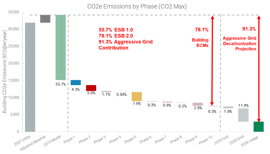
The analysis of the energy modeling results can be facilitated by the creation of ECM waterfall charts which show the baseline energy consumption / carbon emissions and the progressive impact of each ECM on these values. The final energy consumption and carbon emission of the proposed model will establish the theoretical minimum.
Outputs
Outputs and deliverables of this work include:
Initial energy, carbon, and cost savings for individual ECMs. Based on this initial review and analysis, the team will identify further data collection required to refine the modeling assumptions and improve the accuracy of the outputs.
Actionable information regarding which mutually exclusive ECMs are most impactful and should be advanced to the next phase of modeling.
The maximum theoretical energy savings and carbon reduction for the building. This will give the project team an indication of how many ECMs may need to be implemented to meet the project objectives.
Initial energy cost savings for each measure, which can be used to inform preliminary financial analyses.
Lessons Learned & Key Considerations
Review and question surprising results: When reviewing preliminary energy savings, it is important to make sure that the results make sense and question any surprising results. The energy modeling results are only as accurate as the modeling inputs. These assumptions must be vetted to ensure accurate savings. Data collection during this time will be useful to determine modeling assumptions. Assumptions can also be informed by the insights and advice from industry experts. Energy modeling is an iterative process, and the model will continue to be refined as more information is collected.
Identify high priority ECMs: Preliminary results may indicate that most of the energy savings available are attributable to a select number of ECMs. Implementing these select few ECMs may be all that is required to meet the project’s short-term objectives. The project team should focus on refining the inputs for these high impact ECMs to ensure accurate savings.
Remember many small measures have a cumulative impact: To maximize savings and meet long-term project objectives like 80×50 it is likely that a wider array of ECMs will need to be considered for implementation. This holds true especially for buildings that have undergone recent renovations where the most impactful ECMs have already been executed. In this case it may be necessary to evaluate the cumulative impact of many small measures. Therefore, individual measures with minor carbon reduction impacts should not be dismissed too quickly.
4. Group, Sequence, and Package ECMs
As the Energy and Carbon Modeling phase is progressing, a preliminary financial analysis of individual ECMs will also take place in parallel. Preliminary results from the financial analysis will help inform this phase of modeling. Individual ECMs should not necessarily be discarded based solely on their associated capital cost; expensive ECMs can be grouped together with related financially viable measures to optimize savings and make a more comprehensive business case that maximizes CO2 reduction while still addressing investment return hurdles.
Once ECMs have been grouped, an implementation duration and timeline should be established for each. This will depend on factors like short term project budgets, tenant lease turnover, operational budgets, and maintenance schedules. The ECMs should then be sequenced according to their implementation timeline so that energy savings for each ECM can be captured accordingly.
Finally, several ECM packages should be assembled for owner evaluation. Each package will include a different combination of ECMs to be implemented with varying degrees of cost and carbon impact. This variety will provide the owner with options to choose from when striving to balance the project objectives and constraints.
Inputs
For this task the project team will need the following inputs:
Energy, carbon & cost savings from the proposed energy model
Preliminary ECM capital costs estimates: Preliminary results from the financial analysis will provide approximate NPV values for each ECM based on the projected energy cost savings and capital costs. These results will be used to identify those ECMs that are economically viable on their own, those that are worth pursuing due to large carbon impact, and those that should be discarded at this point due to technical infeasibility, cost, or low carbon impact. Those ECMs that are economically viable on their own may be grouped together with related, and costly, but effective, ECMs to help build a stronger business case.
Outputs
Outputs and deliverables of this task include the following:
Finalized grouped and sequenced ECM list.
Results from Packaged ECMS for Owner consideration.
Activities
Establish the Final List of ECMs: Once a preliminary financial analysis has been conducted and approximate NPV values and energy and reductions are calculated for each ECM, the list of measures should be reviewed and finalized. Typically, ECMs will fall into the 5 categories described below, with associated outcomes:
ECM has a positive NPV and has a large carbon impact. ECM should be considered seriously for implementation. Additional QA/QC should be completed to ensure savings are accurate.
ECMs that has a positive NPV but has a minor carbon impact. ECM should be evaluated collectively with other measures, as the impact of many small measures can compound.
ECM has a positive NPV and has a large carbon impact but is technically challenging or infeasible. ECM should likely be eliminated because it will not seriously be considered for implementation by the Owner or building operations team
ECM has a negative NPV (simple payback may still be within the useful life of the ECM) but has a large carbon impact. Financial case for the ECM should be investigated further – the incorporation of maintenance costs, baseline requirements or planned capex unrelated to emissions reductions, and potential incentives in the financial model may improve the financial performance.
ECM has a negative NPV and a small carbon impact. ECM should be eliminated.
Group and Sequence the ECMs: Once the list of ECMs has been finalized, the project team should determine the anticipated duration of time required for completion and the implementation sequence. There are various considerations that should be understood during this part of the modeling process:
The timing of implementation will be unique to each building and vary depending on the types of existing systems and their age and performance. Well maintained systems may be able to be updated and optimized in the short term and replaced in the long run depending on the project objectives.
The sequence of ECMs will depend on various factors including tenant lease turnover schedules, maintenance schedules, and investment cycles.
Interrelated and codependent ECMs should have the same timeline and/or be sequenced appropriately. Some ECMs should be considered as a group to help make a financial case for optimized carbon reductions.
The impact of the ECMs will decrease as the sequence progresses, and savings will be less than if they were directly compared to the initial baseline. This is because as each new ECM is executed and absorbed into the baseline model, this “new” baseline model against which new ECMs are compared performs more efficiently, thereby decreasing the potential for savings.
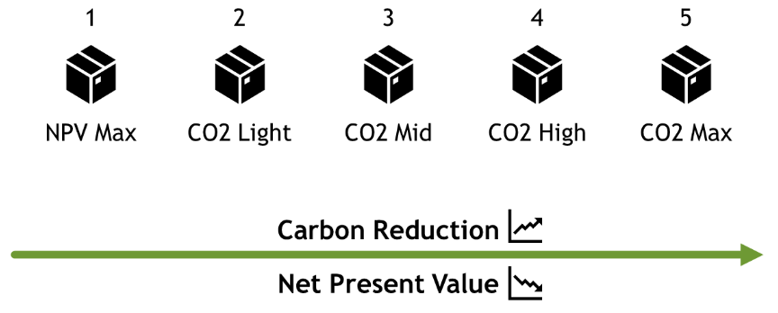
Create ECM Packages: Once the ECMs have been sequenced, various implementation packages should be compiled for final evaluation. Given that implementing all ECMs will likely be cost prohibitive, the project team should provide the owner with different options along the spectrum of project cost and carbon reduction.
To book end the problem, it is recommended that two of the proposed packages be a “CO2 Maximum Reduction” package and an “NPV Maximum” package. These packages are described below:
CO2 Maximum Reduction: Package includes all technically viable measures, even if they are not economically viable at the time of the analysis. The purpose of this package is to find the technical maximum CO2 reductions achievable.
NPV Maximum: Package includes only those measures that payback within the study period and have positive NPVs. These are the minimum CO2 reductions that can be expected with a financially viable package.
Additional packages should be created and evaluated based on feedback from the project team. These hybrid packages will allow the owner to choose from a wide range of options with different value propositions.
Lessons Learned & Key Considerations
Visualize the results: A helpful tool for analyzing ECMs results is a 2 x 2 matrix that shows the NPV vs. the CO2 reductions for each ECM.
Consider non-energy benefits: Before eliminating measures because they have small carbon impacts, the project team should evaluate the non-energy benefits of the measure. If the non-energy benefits align with the owner’s overall sustainability strategy or make the building a more valuable asset, the building team may still wish to pursue the item. For example, a façade upgrade or replacement may not have a positive NVP but will make the building more competitive with newer buildings.
5. Generate a Decarbonization Roadmap
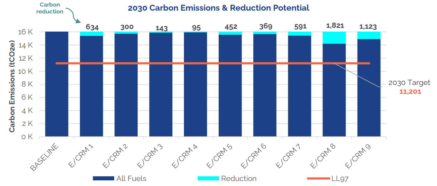
Once the finalized ECMs have been grouped, sequenced, and packaged, the energy model can be run to obtain final results. These results will be used in the detailed financial analysis and will represent a time-dependent decarbonization roadmap for the building. The final results will include energy savings, energy cost, and CO2 reduction for each package under study, and should phased according to the anticipated implementation timeline to reflect the gradual and overlapping impacts of each measure over a 20- or 30-year time horizon. CO2 reduction over a longer time horizon should include a changing electric grid carbon coefficient to account for grid decarbonization.
Inputs
The inputs for this task include:
The finalized ECM Packages
Carbon coefficients for the Future Grid
Activities
Run Final ECM Packages in the Model and Analyze Results: The modeler should update the proposed model based on the final list of ECM packages and intended implementation sequence. Energy results should be provided for each ECM, even if there are several ECMs that are intended to be grouped together, as this provides granular data for the financial analysis to be conducted down the line. This is important because each ECM may have distinct capital costs, maintenance costs, and incentive implications which may impact the financial viability of the measure.
To reduce the modeling time, it may be assumed that a given ECM’s savings are recognized at once, even if it is anticipated that the ECM and associated savings will be realized over a period of several years. These savings can be split proportionally according to the intended timeline in a post-processing exercise without a major impact on the results, so long as the sequence of the ECMs is correct.
Calculate Savings from the Baseline: The final run of the proposed energy model will produce energy, carbon and cost information that should be compared to the baseline energy model to determine anticipated savings. During this exercise, project teams should consider the following:
The energy model provides energy costs for each run, but it may be beneficial to conduct advanced tariff analysis that evaluates the anticipated annual hourly energy consumption for each package. Given the energy consumption results from the model, and the implementation timeline, a composite file of hourly data can be created to accurately reflect the percentage of each ECM that has been implemented each year. This will result in an energy consumption profile that reflects the expected annual peak and associated demand charges. More accurate utility costs can be calculated using this information. At a minimum, a utility cost escalator should be applied to the initial calculated energy cost savings to capture the impact of changing rates over time.
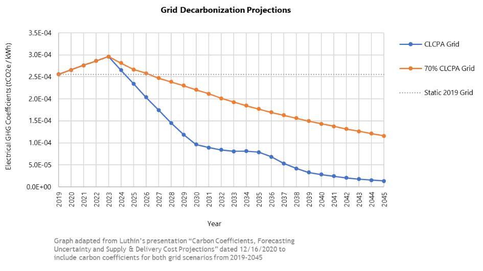
The anticipated CO2 emissions reductions associated with each ECM can be calculated by overlaying today’s carbon coefficients onto the energy savings results. For a greater level of accuracy, the carbon coefficients from LL97 can be overlaid on the annual energy consumption for the years where this data is available (2024-2029). Beyond 2029, project teams should consider different electrical grid decarbonization projections and overlay evolving carbon coefficients on the yearly energy consumption. For example, New York’s Climate Leadership and Community Protection Act (CLCPA) targets 70% renewable energy by 2030. Assuming the grid meets the goals and schedule of the CLPCA, the carbon coefficient for electricity for the year 2030 will be much lower than it is today.
Outputs
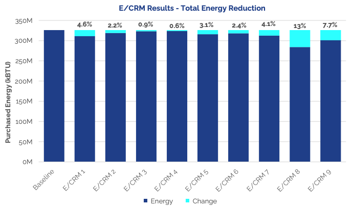
The final energy modeling results should include energy savings, energy cost savings, and CO2 reduction for each ECM package studied.
Lessons Learned & Key Considerations
Total carbon emissions depend on the building and the grid: While building owners have control over how efficient their building is, they cannot control the long-term decarbonization of the electrical grid. Building owners can and should evaluate how they can optimize the energy performance of their building through the implementation of ECMs, but the total associated carbon emissions produced by the building will depend on both the magnitude of the energy consumed and how carbon-intensive the source of energy is. For this reason, it is beneficial to understand how different grid scenarios and emissions factors impact the ECM results. A cleaner grid in 2030 may be the difference between meeting or exceeding the LL97 emissions limit for that year.
A baseline assessment is key to understanding current systems and performance, then identifying conditions, requirements or events that will trigger a decarbonization effort. The assessment looks across technical systems, asset strategy and sectoral factors.
Building System Conditions
Asset Conditions
Market Conditions
Step 2
Step 2: Design Resource Efficient Solutions
Effective engineering integrates measures for reducing energy load, recovering wasted heat, and moving towards partial or full electrification. This increases operational efficiencies, optimizes energy peaks, and avoids oversized heating systems, thus alleviating space constraints and minimizing the cost of retrofits to decarbonize the building over time.
Step 3
Step 3: Build the Business Case
Making a business case for strategic decarbonization requires thinking beyond a traditional energy audit approach or simple payback analysis. It assesses business-as-usual costs and risks against the costs and added value of phased decarbonization investments in the long-term.
Decarbonization Costs
Business-as-Usual Costs
Business-as-Usual Risks
Decarbonization Value
Net Present Value
Strategic Decarbonization Action Plan
An emissions decarbonization roadmap helps building owners visualize their future emissions reductions by outlining the CO2 reductions from selected energy conservation measures. This roadmap is designed with a phased approach, considering a 20- or 30-year timeline, and incorporates the evolving benefits of grid decarbonization, ensuring a comprehensive view of long-term environmental impact.
Project Team
Additional Resources
Tags
This guide presents a three-step process for real estate owners, in coordination with engineers and designers, to develop a technically and economically feasible decarbonization plan for their building. This holistic approach is informed by lessons learned from low-carbon demonstration projects funded through the Empire Building Challenge to help building owners develop and adopt successful plans for retrofitting their building.
A Rational Approach to Large Building Decarbonization
Tags
Project Highlights
Step 1
Step 1: Examine Current Conditions
A baseline assessment is key to understanding current systems and performance, then identifying conditions, requirements or events that will trigger a decarbonization effort. The assessment looks across technical systems, asset strategy and sectoral factors.
Building System Conditions
Asset Conditions
Market Conditions
Step 2
Step 2: Design Resource Efficient Solutions
Effective engineering integrates measures for reducing energy load, recovering wasted heat, and moving towards partial or full electrification. This increases operational efficiencies, optimizes energy peaks, and avoids oversized heating systems, thus alleviating space constraints and minimizing the cost of retrofits to decarbonize the building over time.
Step 3
Step 3: Build the Business Case
Making a business case for strategic decarbonization requires thinking beyond a traditional energy audit approach or simple payback analysis. It assesses business-as-usual costs and risks against the costs and added value of phased decarbonization investments in the long-term.
Decarbonization Costs
Business-as-Usual Costs
Business-as-Usual Risks
Decarbonization Value
Net Present Value
Strategic Decarbonization Action Plan
An emissions decarbonization roadmap helps building owners visualize their future emissions reductions by outlining the CO2 reductions from selected energy conservation measures. This roadmap is designed with a phased approach, considering a 20- or 30-year timeline, and incorporates the evolving benefits of grid decarbonization, ensuring a comprehensive view of long-term environmental impact.
Project Team
Additional Resources
Tags
Lessons from New York’s Empire Building Challenge
This article, published in NESEA’s BuildingEnergy magazine (Vol. 40 No. 1), addresses common “decarbonization blind spots” that impede progress and shares insights gained from the incremental methodology and integrated design process pioneered through NYSERDA’s Empire Building Challenge.
A baseline assessment is key to understanding current systems and performance, then identifying conditions, requirements or events that will trigger a decarbonization effort. The assessment looks across technical systems, asset strategy and sectoral factors.
Building System Conditions
Asset Conditions
Market Conditions
Step 2
Step 2: Design Resource Efficient Solutions
Effective engineering integrates measures for reducing energy load, recovering wasted heat, and moving towards partial or full electrification. This increases operational efficiencies, optimizes energy peaks, and avoids oversized heating systems, thus alleviating space constraints and minimizing the cost of retrofits to decarbonize the building over time.
Step 3
Step 3: Build the Business Case
Making a business case for strategic decarbonization requires thinking beyond a traditional energy audit approach or simple payback analysis. It assesses business-as-usual costs and risks against the costs and added value of phased decarbonization investments in the long-term.
Decarbonization Costs
Business-as-Usual Costs
Business-as-Usual Risks
Decarbonization Value
Net Present Value
Strategic Decarbonization Action Plan
An emissions decarbonization roadmap helps building owners visualize their future emissions reductions by outlining the CO2 reductions from selected energy conservation measures. This roadmap is designed with a phased approach, considering a 20- or 30-year timeline, and incorporates the evolving benefits of grid decarbonization, ensuring a comprehensive view of long-term environmental impact.
Project Team
Additional Resources
Tags
Insights from Empire Building Challenge
Large commercial and residential buildings must overcome various hurdles before implementing deep retrofits or capital projects that help achieve building decarbonization. This section addresses technical barriers and questions often faced by building owners and retrofit project developers.
Decentralized Systems and Tenant Equipment
Access to Occupied Spaces.
Lease Concerns.
Regulatory Limitations of Rent Stabilized Apartments.
The building owner is required to provide free heat and hot water.
No mechanism to recover investment in new systems is necessary to achieve decarbonization.
Buildings are capital constrained.
Split Incentives (e.g. tenants pay for energy).
Facade and Windows
Work must be completed at the end of facade/window useful life; very long useful life.
Building codes.
Glazing reduction at odds with aesthetic/marketability concerns.
Difficult installing with occupied spaces.
Reduce Local Law 11 recurring cost via overcladding
Aesthetic concerns
At odds with historic preservation
Capital intensive
Lot line limitations
Technology Limitations
Need higher R-value/inch for thinner wall assembly:
Vacuum insulated panels
Aerogel panels/batts
Zero-GWP blowing agents for closed cell spray foam (nitrogen blowing agent needs to be more widely adopted)
Ventilation
Energy Recovery Ventilation (ERV)
Space constraints
System tie-in point accessibility/feasibility
Rooftop Supply Air (Reznor) Unit Alternatives
Heat pump alternatives to eliminate resistance heat
Combine with ERV
HVAC Load Reduction (HLR) Technology
Vent or capture exhaust gases
Space constraints
System tie-in point accessibility/feasibility
Central vs. Decentralized Ventilation Systems
Direct Outside Air System (DOAS)
Modular perimeter ducted air heat pumps:
Competition for leasable space
Space constraints
Ventilation Points-of-Entry
Aesthetic concerns
Lot line facades/building setbacks
Competition with leasable space
Space constraints
Heat Pump Limitations
Variable Refrigerant Flow (VRF)
Fire and life safety concerns about volume of refrigerant gas located within occupied spaces.
Regulatory risk from new refrigerant policies
PTAC and VTAC
Ducted Supply/Exhaust Air Source Heat Pumps
Domestic Hot Water
Central DHW Systems:
Limited domestic production.
Performance not confirmed by independent third parties.
More demonstration projects needed.
Decentralized DHW Systems
More open-source interconnection between devices/interoperability is needed to achieve energy distribution flexibility and capacity expansion:
Air source that has a manifold connection to interconnect with water source or refrigerant gas distribution.
Interconnectivity/simplified heat exchange between refrigerants/water/air, etc.
Other options and add-ons.
Steam Alternatives and Barriers
Below are high temperature renewable resource alternatives to district steam. These alternatives are limited and face barriers to implementation due to cost, scalability, and other factors.
Deep Bore Geothermal
Renewable Hydrogen
Carbon Capture and Sequestration
Biomethane
Electric Boilers
High-temperature thermal storage
Hight-temperature industrial heat pumps
Waste Heat Capture and Reuse
Fission
Barriers to Electrification and Utility Capacity Limitations
Building Electric Capacity Upgrades
Electric riser capacity
Switchgear expansion
New service/vault expansion/point-of-entry space constraints
Capacity competition with other electrification needs:
Space heat and cooling
DHW
Cooking
Pumps and motors
Local Network Electric Capacity Upgrades
Excess Distribution Facility Charges (EDF)
Contributions in Aid of Construction (CIAC)
Gas Utility Earnings Adjustment Mechanisms (EAM) focused on System Peak Demand Reductions
Partial Electrification concepts achieve deep decarbonization but do not necessarily achieve peak gas demand reductions (debatable)
Total Connected Loads and Peak Demand drive need for capacity upgrades
Demand reduction strategies do not obviate capacity limitations unless the utility accepts the solution as a permanent demand/load reduction strategy.
Battery Storage:
Fire danger
Space constraints
Electricity distribution limitations
Structural loads
Building Automation/BMS/Demand Response:
Cost
Integration limitations; Blackbox software
Microgrid development cost and lack of expertise
On-site Generation:
Space constraints
Gas use; Zero carbon fuels availability is non-existent
Structural loads
Pipe infrastructure
Thermal Storage
Space constrains
Structural loads
Technology limitations:
Vacuum insulated storage tanks
Phase change material (DHW, space heating)
Geothermal (ambient temperature), Deep Bore Geothermal (high temperature) or Shared Loop District Energy Systems provide cooling and heating with lower peak demand than standard electric equipment
Building pipe riser limitations; need additional riser capacity:
Building water loops are typically “top down” – cooling capacity is typically located at rooftop mechanical penthouses; cooling towers at roof. Some exceptions to this rule
Space Constraints
Drilling Difficulty:
Outdoor space constraints for geothermal wells
Difficult permitting
Mud and contaminated soil disposal
Overhead clearance constraints for drilling in basements/garages
Shared Loop/Thermal Utility Limitations:
Requires entity that may operate in public ROWs and across property lines
Utilities are limited by regulations for gas, steam or electric delivery versus shared loop media (ambient temperature water).
Only utility entities can provide very long amortization periods
Utilities are best suited to work amid crowded underground municipal ROWs.
Deep Bore Geothermal Limitations:
Requires test drilling and geological assessment
Seismic risk
Drilling equipment is very large – more akin to oil and gas development equipment
Subsurface land rights and DEC restrictions
Other Energy Efficiency/Conservation Measures with proven/attractive economics (these measures are limited by lack of capital or knowledge)
A baseline assessment is key to understanding current systems and performance, then identifying conditions, requirements or events that will trigger a decarbonization effort. The assessment looks across technical systems, asset strategy and sectoral factors.
Building System Conditions
Asset Conditions
Market Conditions
Step 2
Step 2: Design Resource Efficient Solutions
Effective engineering integrates measures for reducing energy load, recovering wasted heat, and moving towards partial or full electrification. This increases operational efficiencies, optimizes energy peaks, and avoids oversized heating systems, thus alleviating space constraints and minimizing the cost of retrofits to decarbonize the building over time.
Step 3
Step 3: Build the Business Case
Making a business case for strategic decarbonization requires thinking beyond a traditional energy audit approach or simple payback analysis. It assesses business-as-usual costs and risks against the costs and added value of phased decarbonization investments in the long-term.
Decarbonization Costs
Business-as-Usual Costs
Business-as-Usual Risks
Decarbonization Value
Net Present Value
Strategic Decarbonization Action Plan
An emissions decarbonization roadmap helps building owners visualize their future emissions reductions by outlining the CO2 reductions from selected energy conservation measures. This roadmap is designed with a phased approach, considering a 20- or 30-year timeline, and incorporates the evolving benefits of grid decarbonization, ensuring a comprehensive view of long-term environmental impact.
Project Team
Additional Resources
Tags
These playbooks summarize retrofit strategies that maximize occupant comfort and energy savings through a transition from fuel to electricity- based heating, cooling and hot water systems.
Playbooks are organized by building system— lighting & loads, envelope, ventilation, heating & cooling, and domestic hot water– detailing common existing systems, typical issues, and recommended measures.
A baseline assessment is key to understanding current systems and performance, then identifying conditions, requirements or events that will trigger a decarbonization effort. The assessment looks across technical systems, asset strategy and sectoral factors.
Building System Conditions
Asset Conditions
Market Conditions
Step 2
Step 2: Design Resource Efficient Solutions
Effective engineering integrates measures for reducing energy load, recovering wasted heat, and moving towards partial or full electrification. This increases operational efficiencies, optimizes energy peaks, and avoids oversized heating systems, thus alleviating space constraints and minimizing the cost of retrofits to decarbonize the building over time.
Step 3
Step 3: Build the Business Case
Making a business case for strategic decarbonization requires thinking beyond a traditional energy audit approach or simple payback analysis. It assesses business-as-usual costs and risks against the costs and added value of phased decarbonization investments in the long-term.
Decarbonization Costs
Business-as-Usual Costs
Business-as-Usual Risks
Decarbonization Value
Net Present Value
Strategic Decarbonization Action Plan
An emissions decarbonization roadmap helps building owners visualize their future emissions reductions by outlining the CO2 reductions from selected energy conservation measures. This roadmap is designed with a phased approach, considering a 20- or 30-year timeline, and incorporates the evolving benefits of grid decarbonization, ensuring a comprehensive view of long-term environmental impact.
Project Team
Additional Resources
Tags
The Empire Technology Prize is a $10 million competitive opportunity for global solution providers focused on advancing building technologies for low-carbon heating system retrofits in tall commercial and multifamily buildings across New York State. This NYSERDA initiative, administered by The Clean Fight with technical support from Rocky Mountain Institute, includes a $3 million sponsorship from Wells Fargo. Accelerating low-carbon building retrofits is fundamental to New York State’s national-leading Climate Act agenda, including the goal to achieve an 85% reduction in greenhouse gas emissions by 2050.
A baseline assessment is key to understanding current systems and performance, then identifying conditions, requirements or events that will trigger a decarbonization effort. The assessment looks across technical systems, asset strategy and sectoral factors.
Building System Conditions
Asset Conditions
Market Conditions
Step 2
Step 2: Design Resource Efficient Solutions
Effective engineering integrates measures for reducing energy load, recovering wasted heat, and moving towards partial or full electrification. This increases operational efficiencies, optimizes energy peaks, and avoids oversized heating systems, thus alleviating space constraints and minimizing the cost of retrofits to decarbonize the building over time.
Step 3
Step 3: Build the Business Case
Making a business case for strategic decarbonization requires thinking beyond a traditional energy audit approach or simple payback analysis. It assesses business-as-usual costs and risks against the costs and added value of phased decarbonization investments in the long-term.
Decarbonization Costs
Business-as-Usual Costs
Business-as-Usual Risks
Decarbonization Value
Net Present Value
Strategic Decarbonization Action Plan
An emissions decarbonization roadmap helps building owners visualize their future emissions reductions by outlining the CO2 reductions from selected energy conservation measures. This roadmap is designed with a phased approach, considering a 20- or 30-year timeline, and incorporates the evolving benefits of grid decarbonization, ensuring a comprehensive view of long-term environmental impact.
Project Team
Additional Resources
Tags
Insights from Empire Building Challenge
Prioritizing Decarbonization Interventions
While each individual building has a unique capital improvement plan and timeline, retrofit projects or decarbonization interventions may be organized and grouped by similarity as property owners plan for the future. Below is the overarching hierarchy for decarbonization intervention points according to industry best practices:
Facade Upgrades
Windows Upgrades
Ventilation Upgrades with Energy Recovery Ventilators (ERV)
Maximize the reduction of distribution temperatures
Maximize surface area of terminal units
Supplement 90% of peak load with hybrid electrification strategies
Eliminate peak load “last-mile” with innovative strategies in storage and/or thermal demand response
Delay replacement of gas-fired equipment with new gas-fired equipment as long as possible. Rebuild and maintain existing equipment until replacement.
Replace all remaining non-LED lighting and include lighting controls at the time of retrofit
Seal rooftop bulkhead doors and windows.
Add smoke-activated fire dampers or annealed glass to the elevator shaft vent grill in the elevator machine room.
Install algorithmic controls on top of the existing boiler control system.
Balance steam distribution systems:
Identify condensate return leaks.
Right-size air vents and master vents.
Ensure all radiators are properly draining condensate.
Ensure all steam traps are functioning properly.
Implement Radiator Efficiency and Controls Measures:
Install thermostatic radiator valves (TRV) where possible.
Install RadiatorLabs radiator cover systems where possible (integrate with algorithmic boiler control).
Balance air supply and ventilation systems using proper air registers, louvers, dampers, and technology like Constant Airflow Regulator (CAR) dampers:
Need innovative methods of balancing temperature across commercial office floors (heat shifting and sharing from one building exposure to another, e.g. north vs. south).
Balance air supply and return across vertical pressure gradients.
Seal vent stack perforations/leaks (e.g. mastic sealer).
Increase efficiency of pumps and motors:
Add VFD controllers to all pumps and motors.
Replace rooftop exhaust fans (e.g. mushroom fans or similar) with electronic commutated motors.
Implement algorithmic controls on top of existing Building Management Systems (BMS) in commercial office buildings.
Hybrid Domestic Hot Water (DHW) Plants: Add DHW heat pump equipment to an existing gas fired DHW plant.
Consider the option to direct bathroom exhaust air to DHW heat pump equipment.
Install Energy Recovery Ventilation (ERV) system.
Install rooftop solar.
Procure New York State-sourced renewable power.
Procure biomethane from utility via pilot program.
Procure renewable hydrogen blend from utility via pilot program.
Develop innovative means of participating in gas demand response:
Delay boiler firing with controls or other means.
Procure biodiesel blend for fuel switching requirement.
Thermal storage and hybrid plants (electrification)
DHW electrification (partial or full load)
Split system or PTAC partial load heating electrification
Add central-control compatible thermostats to apartments and office suites to control decentralized heating and cooling systems.
Enable aggregate demand response activity.
Fully electrify DHW systems:
Air source DHW heat pump.
Resistance DHW.
High-efficiency thermal storage.
Supplement with solar thermal where compatible.
Overlaid or insulated masonry facades with high ongoing Local Law 11 cost.
Eliminate uninsulated radiator cabinets/niches in exterior walls.
Install wall-mounted slim radiators with TRV or other controls.
Install RadiatorLabs technology.
Begin routine window replacement plan with high-performance windows.
Support cogeneration systems with biomethane (injection) procurement.
Explore hydrogen (injection) procurement to support cogeneration and centralized heating plants.
Develop on-site battery storage systems to manage building load profiles and reduce peak usage.
Integrate with an existing on-site generation where compatible.
Increase thermal mass/thermal inertia and expand thermal storage capacity using Phase Change Material (PCM) products. Products currently include: ceiling tiles, wall panels, AHU inserts, thermal storage tank inserts:
Embrace overnight free cooling.
Shift loads associated with thermal demand.
Capture and store waste heat.
Implement centralized or in-building distributed thermal storage systems to shift thermal loads to off-peak periods.
Convert low-temperature heating distribution systems to shared loop systems or geothermal systems; building distribution is already optimized for low-temperature distribution: water source heat pumps, large surface area terminal units (radiant panels, underfloor heat, fan coils, etc.)
Interconnect with early shared loop system phases (private or utility-led).
Eliminate cooling tower as a primary cooling system (may remain as a backup as feasible).
Where necessary, convert high-temperature heating distribution systems to low-temperature distribution systems; systems converted from fin tube to radiant panels, fan coils, or water source heat pumps as feasible.
The supplement heat source for hydronic heat pumps with solar thermal technology (water source heat pumps).
Embrace consumer products that reduce building loads and peak demand:
Appliances with onboard battery storage.
Networked smart appliances.
Power over Ethernet (PoE) DC-powered, low voltage products.
DC power distribution networks make use of on-site renewable energy and energy storage.
Advanced DC[1] and AC/DC hybrid Power Distribution Systems[2]
Install HVAC Load Reduction Technology:
Capture VOCs and CO2 in liquid sorbent.
Engage with the liquid sorbent management company to safely dispose of scrubbed gases (carbon sequestration, etc.).
Use buildings hosts for negative carbon technology and focusing on direct air capture to achieve larger decarbonization goals (carbon capture and sequestration)
Electric Distribution Upgrade Needed:
Begin replacement of centralized heating systems with decentralized heating and cooling systems where appropriate. Technology includes: PTAC, VTAC, ducted PTAC, VRF, and similar technology.
Replace stoves, ranges, and cooktops with electric equipment: resistance, convection, or induction.
Integrate Building Distribution with an advanced electric vehicle (EV) charging network to provide power to parked EVs and to extract power at peak periods (EV owners opt-in for reduced parking rates, other benefits, etc.).
Install multi-function glass during window or facade replacement:
Install building-integrated PV during facade retrofits.
PV glass.
Electrochromic glass.
Vacuum Insulated glass.
Install highly insulated panels at spandrels:
Vacuum insulated panels.
Aerogel insulated panels.
Replace cooling towers with advanced heat rejection technology:
Passive radiative cooling technology.
Interconnect with 100% hydrogen distribution network.
Pair advanced, on-site battery storage systems with hydrogen fuel cells.
Located in Yonkers, NY, Whitney Young Manor, is a notable affordable housing complex with 195 apartments across 234,000 square feet and 12 stories. Built in 1974, the housing complex is now undergoing a $22 million makeover focusing heavily on decarbonization upgrades. This renovation aims to modernize the buildings by improving insulation and introducing a new heating and cooling system that’s energy efficient. These changes are expected to lower the buildings’ carbon footprint, enhance living conditions, and reduce energy costs. The developer, Paths Development LLC, is leveraging the recapitalization cycle of the property to upgrade its infrastructure and include decarbonization measures to meet its climate goals.
Project Highlights
Investment
12 million
of total investment allocated to bring Whitney Young Manor to carbon neutrality by 2035.
Project Scale
Project has potential replication across a portfolio of 51 existing affordable housing developments managed by Paths.
Testimonial
“The Empire Building Challenge is enabling Paths to pilot innovative approaches to decarbonization while at the same time helping to preserve affordable housing.”
Kenneth Spillberg
Head of Development
Paths Development LLC
Emissions Reductions
This project prioritizes intensive load reduction through envelope improvements and hydronic distribution to improve resident comfort while reducing carbon emissions, utility spend and maintenance costs.
Step 1
Step 1: Examine Current Conditions
A baseline assessment is key to understanding current systems and performance, then identifying conditions, requirements or events that will trigger a decarbonization effort. The assessment looks across technical systems, asset strategy and sectoral factors.
Building System Conditions
Equipment nearing end-of-life
New heat source potential
Comfort improvements
Indoor air quality improvements
Facade maintenance
Resilience upgrades
Efficiency improvements
Asset Conditions
Recapitalization
Carbon emissions limits
Owner sustainability goals
Market Conditions
Technology improves
Utility prices change
Fuels phase out
Whitney Young Manor is an aging affordable housing complex with open balconies, inefficient electric resistance baseboard heating, electric wall sleeve AC units, and gas-fired domestic hot water heaters.
The project team believes that with care, planning, and the appropriate resources, retrofitting these residential buildings can better serve tenants, deliver environmental benefits, and prove financially feasible for owners. Paths leverages the recapitalization cycle of the property to upgrade its infrastructure and include decarbonization measures to meet its climate goals.
This project prioritizes intensive load reduction through envelope improvements and hydronic distribution to improve resident comfort while reducing carbon emissions, utility spending, and maintenance costs.
Step 2
Step 2: Design Resource Efficient Solutions
Effective engineering integrates measures for reducing energy load, recovering wasted heat, and moving towards partial or full electrification. This increases operational efficiencies, optimizes energy peaks, and avoids oversized heating systems, thus alleviating space constraints and minimizing the cost of retrofits to decarbonize the building over time.
Existing Conditions
This diagram illustrates the building prior to the initiation of Strategic Decarbonization planning by the owners and their teams.
Click through the measures under “Building After” to understand the components of the building’s energy transition.
Sequence of Measures
2024
2025
Building System Affected
heating
cooling
ventilation
Reduce Energy Load
Whitney Young Manor demonstrates the benefits of over- cladding and hydronic distribution to enable heat pump technology:
New hydronic distribution: High efficiency water-based distribution system, lower supply temperature
The new hydronic distribution piping will enable the integration of different heating sources and allow heat sharing between end uses, such as DHW production during cooling season. The construction team plans to pilot cross-linked polyethylene (PEX) piping to reduce cost and improve durability.
Dedicated Outside Air System (DOAS): decouple ventilation from heat and cooling systems
Envelope Improvements: overclad, roof insulation and window replacement
Over-cladding using Exterior Insulation and Finishing System (EIFS) helps reduce heat loss and air infiltration while avoiding façade maintenance costs associated with LL11. This measure is combined with the new Dedicated Outside Air System (DOAS) to make sure adequate fresh air is injected into the building.
Recover Wasted Heat
The project team plans to integrate different heat sources connected to the central hydronic piping. This includes centralized air source heat pumps, Wastewater Energy Transfer (WET) system and gas-fired condensing boilers as back-up.
Wastewater Heat Recovery: Recapture heat from wastewater using WSHP
Energy Recovery Ventilator (ERV): Recapture heat from ventilation exhaust to condition make-up air
Electrification
Central Air Source Heat Pump (ASHP): Maintain design temperatures for the hydronic loop
Water Source Heat Pump (WSHP) for Domestic Hot Water (DHW): DHW production supplied by hydronic loop
Back-up gas condensing boiler: Provide supplemental heat during cold events as resiliency
Step 3
Step 3: Build the Business Case
Making a business case for strategic decarbonization requires thinking beyond a traditional energy audit approach or simple payback analysis. It assesses business-as-usual costs and risks against the costs and added value of phased decarbonization investments in the long-term.
Decarbonization Costs
$12M
Capital costs of decarbonization measures.
Business-as-Usual Costs
$1.92M
Energy cost savings, repairs and maintenance savings, BAU cost of system replacement and upgrades.
Business-as-Usual Risks
N/A
LL97 emissions fines don’t apply at this property.
Decarbonization Value
$6.14M
Incentives from Empire Building Challenge, Low-Carbon Pathways Program, and ConEd Clean Heat.
Net Present Value
TBD
Net difference between the present value of cash inflows and outflows over a period of time.
Paths Development LLC is a division of Paths, a full-scale, vertically integrated affordable housing developer, builder, and operator. Since 2004, the Paths team has created and preserved high-quality affordable housing across the U.S. that enhances communities and helps residents build better lives. With other 12,000 units across 9 states under management and more than 300 employees, Paths manages a suite of capabilities spanning the entire property life-cycle, including: development, construction, property management, maintenance, and security.
Strategic Decarbonization Action Plan
An emissions decarbonization roadmap helps building owners visualize their future emissions reductions by outlining the CO2 reductions from selected energy conservation measures. This roadmap is designed with a phased approach, considering a 20- or 30-year timeline, and incorporates the evolving benefits of grid decarbonization, ensuring a comprehensive view of long-term environmental impact.